 In part II of this series of articles I will elaborate on my preliminary findings about the possibly beneficial effect of introducing gaps between adjacent enclosures in cardioid stacks and arrays.
Click here to read Part I.
The conditions for perfect cancellation are very stringent. I've come to call this state the "center of tranquility at the eye of the storm".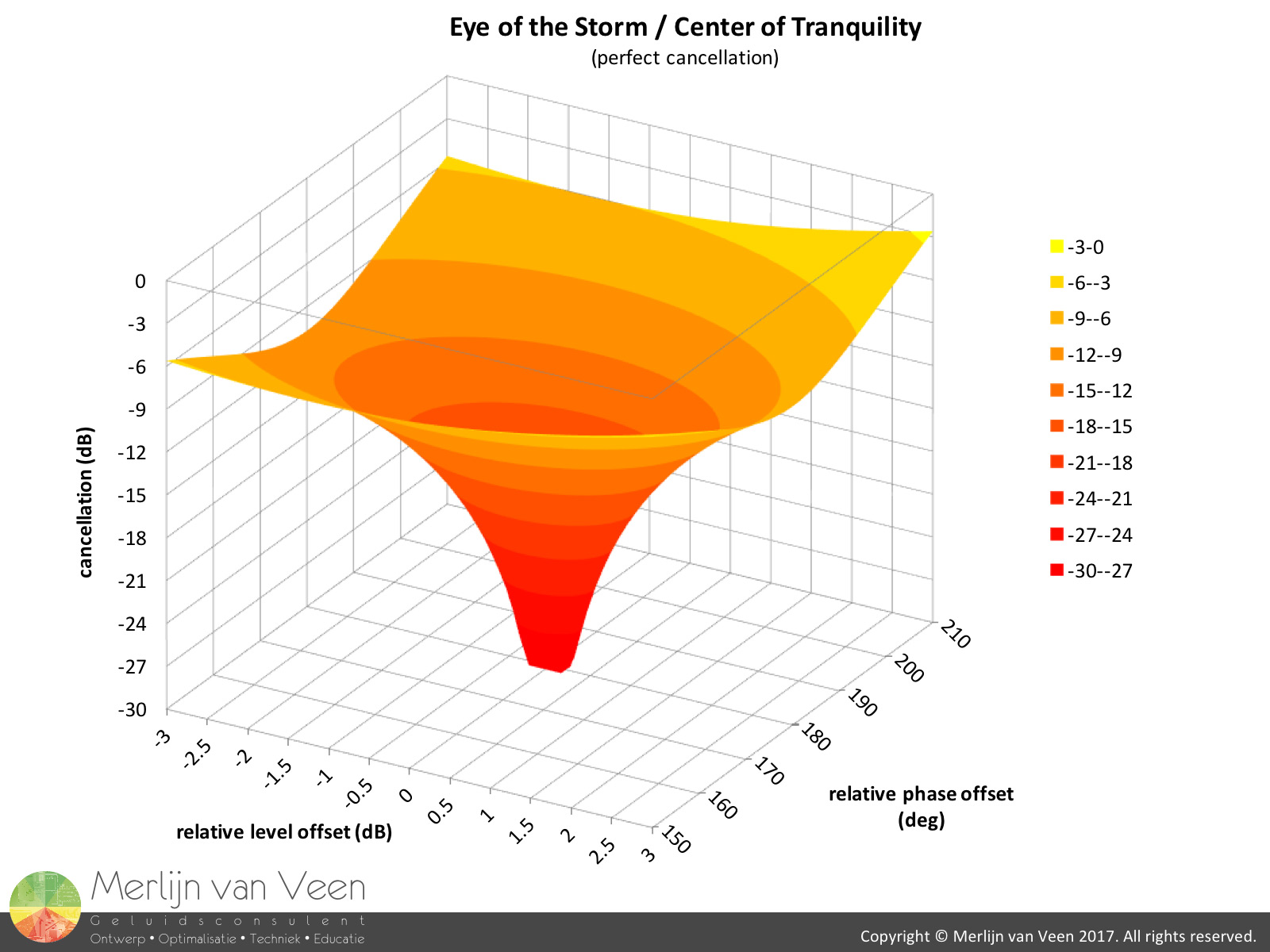 figure 1
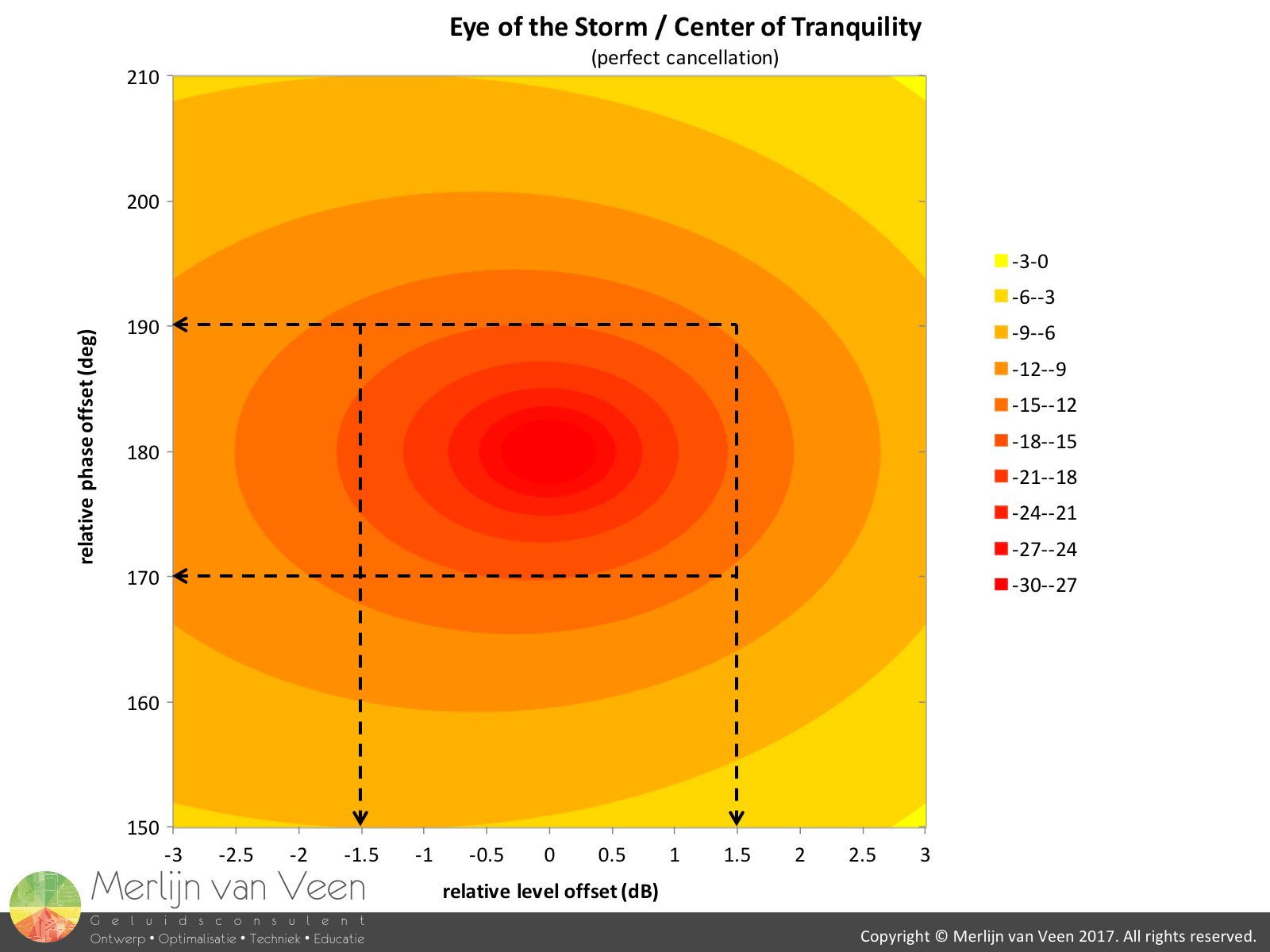 figure 2
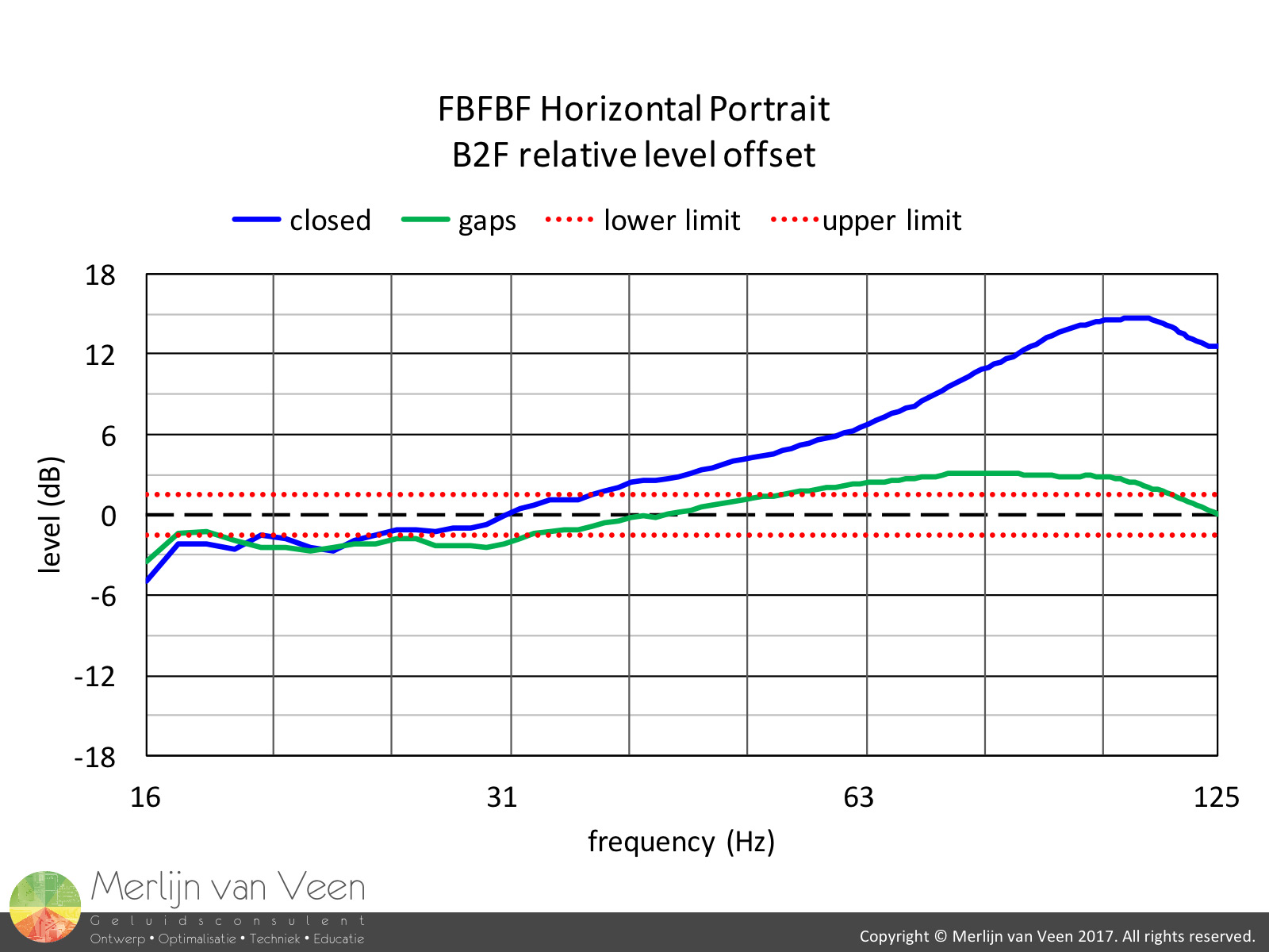 figure 3 Notice how the chart in figure 1 resembles a tornado.
A two dimensional rendering of this chart (figure 2) shows that relative level offsets should remain within ± 1,5 dB and relative phase offsets within ± 10° in order to achieve 15 dB cancellation or more.
Let's look at an example of the measurements I conducted at a former air force base (see Part I for details).
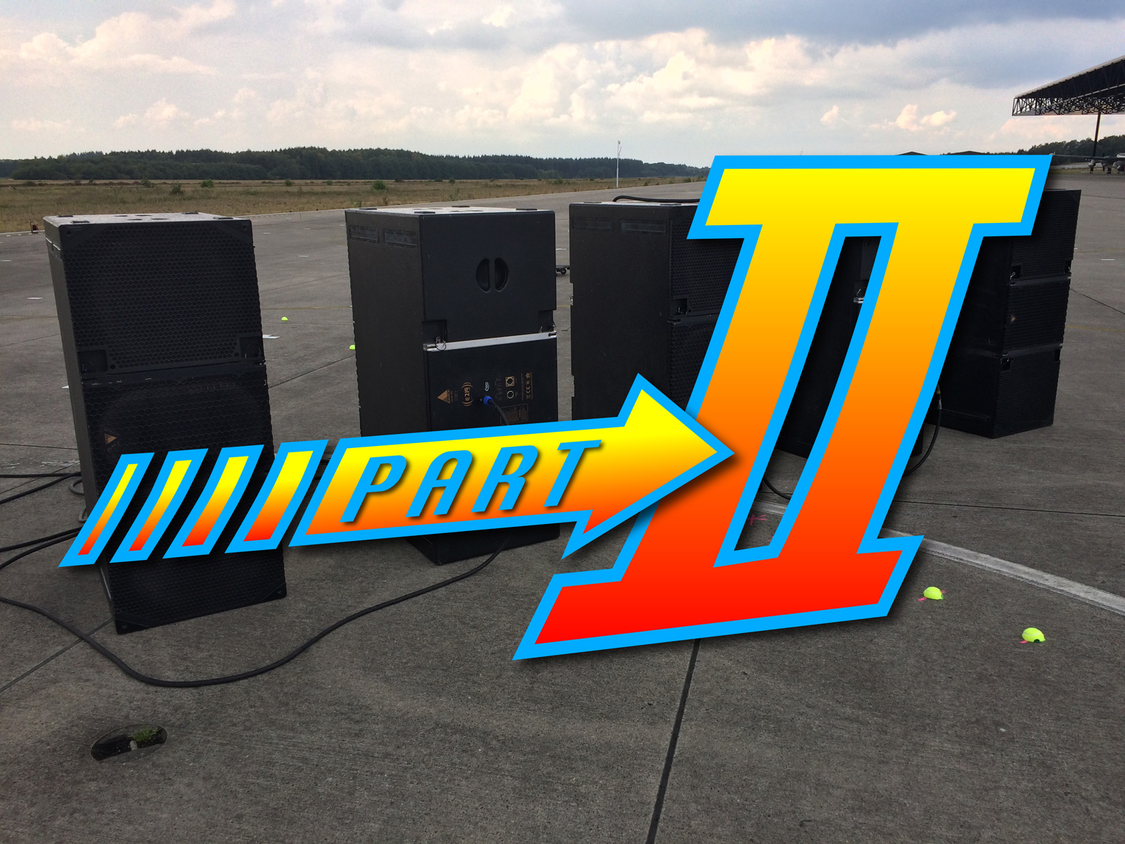
Figure 3 shows the relative Back-2-Front (rear facing vs. front facing subwoofers) level at a distance of 32 m (105 feet) behind a horizontal FBFBF array in portrait orientation (intro image).
Notice the increasing level difference towards higher subwoofer frequencies when the array is closed (without gaps). This is caused by diffraction that increases with the overall baffle size of the entire array. Remaining within the ± 1,5 dB corridor is quite challenging.
Evidently this could easily be remedied with either electronic level adjustments and/or equalization. A practice I refrain from using out of fear of "pattern implosion" when limiters engage at different stages due to these electronic adjustments. Changing the ratio of front- vs rear-facing subwoofers, in my opinion, is a more elegant solution.
With gaps, the diffractive effect is less pronounced (due to the breakup of the combined baffle) and relative level differences remain better predictable. Unless, one has access to e.g. Boundary Element Method (BEM) modeling that exhibits these phenomena.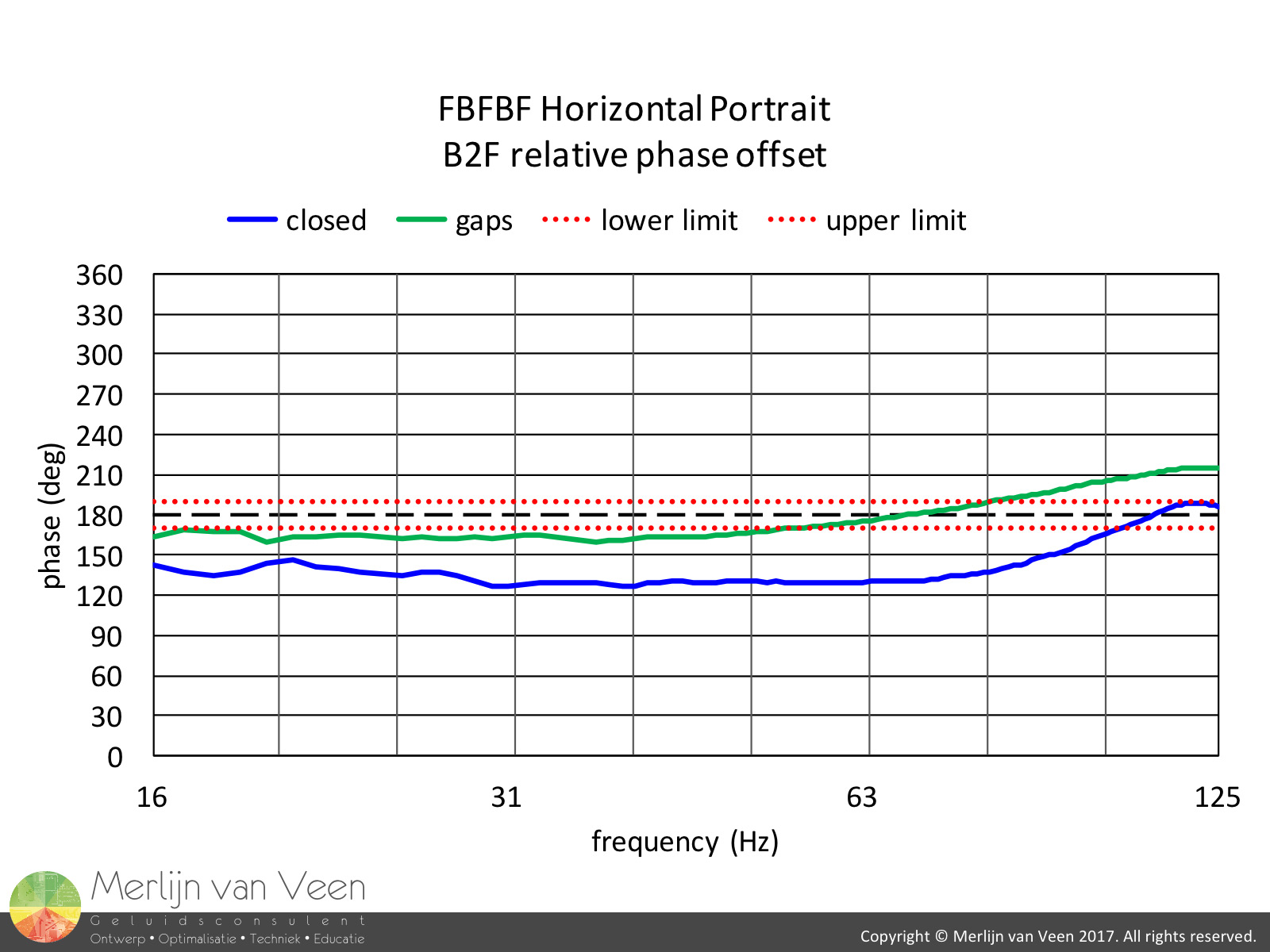 figure 4Figure 4 shows the relative phase offsets. This observation alone, made the entire air force base measurements worthwhile for me personally.
With or without gaps, using the same delay time mandatory for gradient (CSA) setups, has a profound effect on the relative phase offset. Bordering the point that neither cancellation nor summation will occur (120° phase offset).
In his 2006 AES paper called "The Acoustic Center: A New Concept for Loudspeakers at Low Frequencies", professor John Vanderkooy presents analytical proof and compelling evidence suggesting that the acoustic center for subwoofers resides in front of the enclosure. This behavior persists up to frequencies where the physical size of the source is about half a wavelength.
There are three variables that determine the acoustic center position for a subwoofer. Driver radius, baffle radius and enclosure depth. Their effects can be condensed into a single chart (with respect to baffle radius) shown in figure 7. 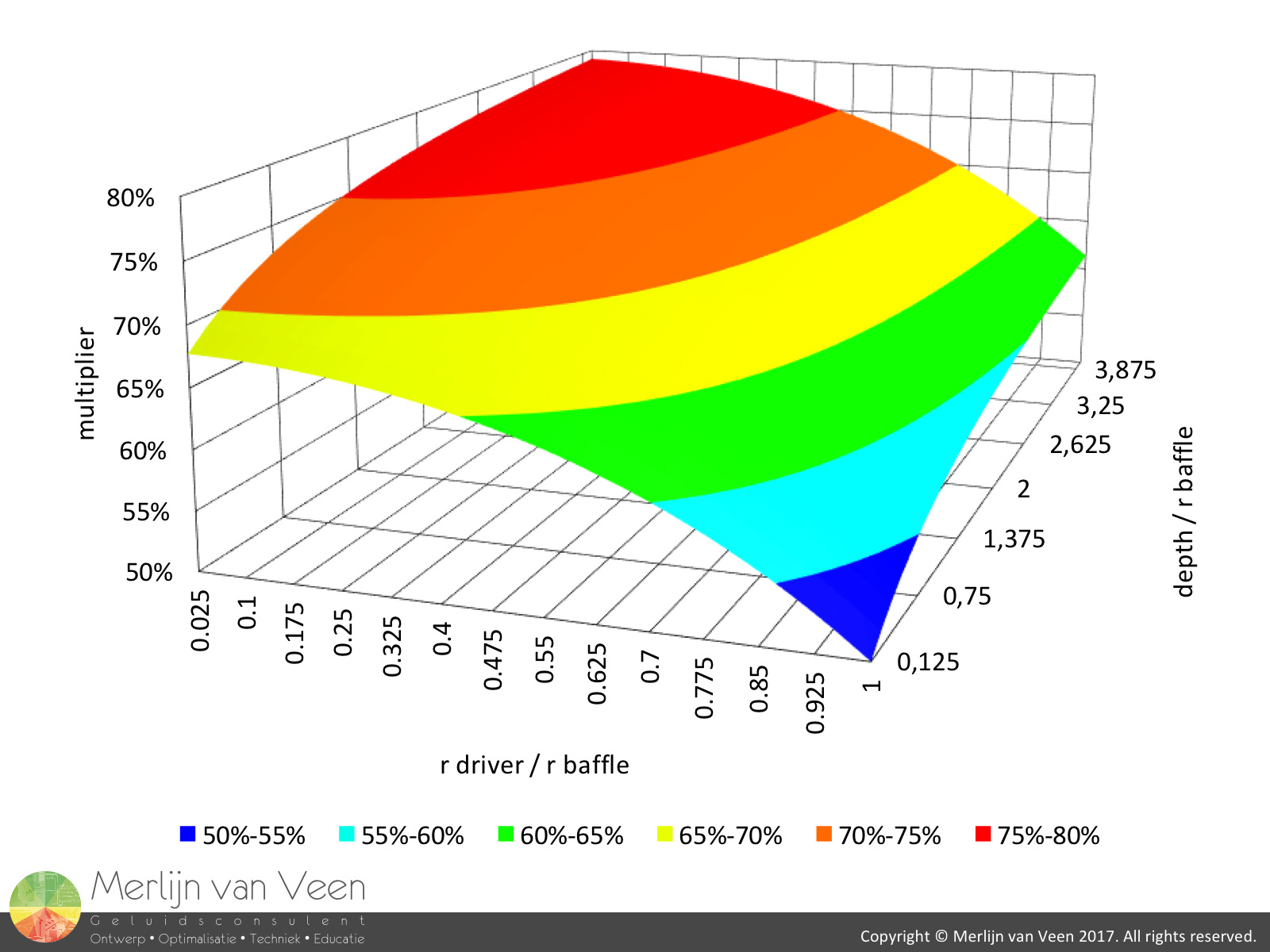 figure 7If the driver radius is relatively small with respect to the baffle radius (x-axis) and/or the enclosure is relatively deep with respect to the baffle radius (y-axis), the acoustic center is propelled outwards by a certain factor or multiplier (z-axis), away from the driver (on axis). This multiplier times the baffle radius will produce the acoustic center distance.
When we build stacks or arrays, the combined baffle area increases. However, due to the alternating orientation of subwoofers in gradient (CSA) configurations, the increase in combined baffle area typically exceeds the increase in combined cone area.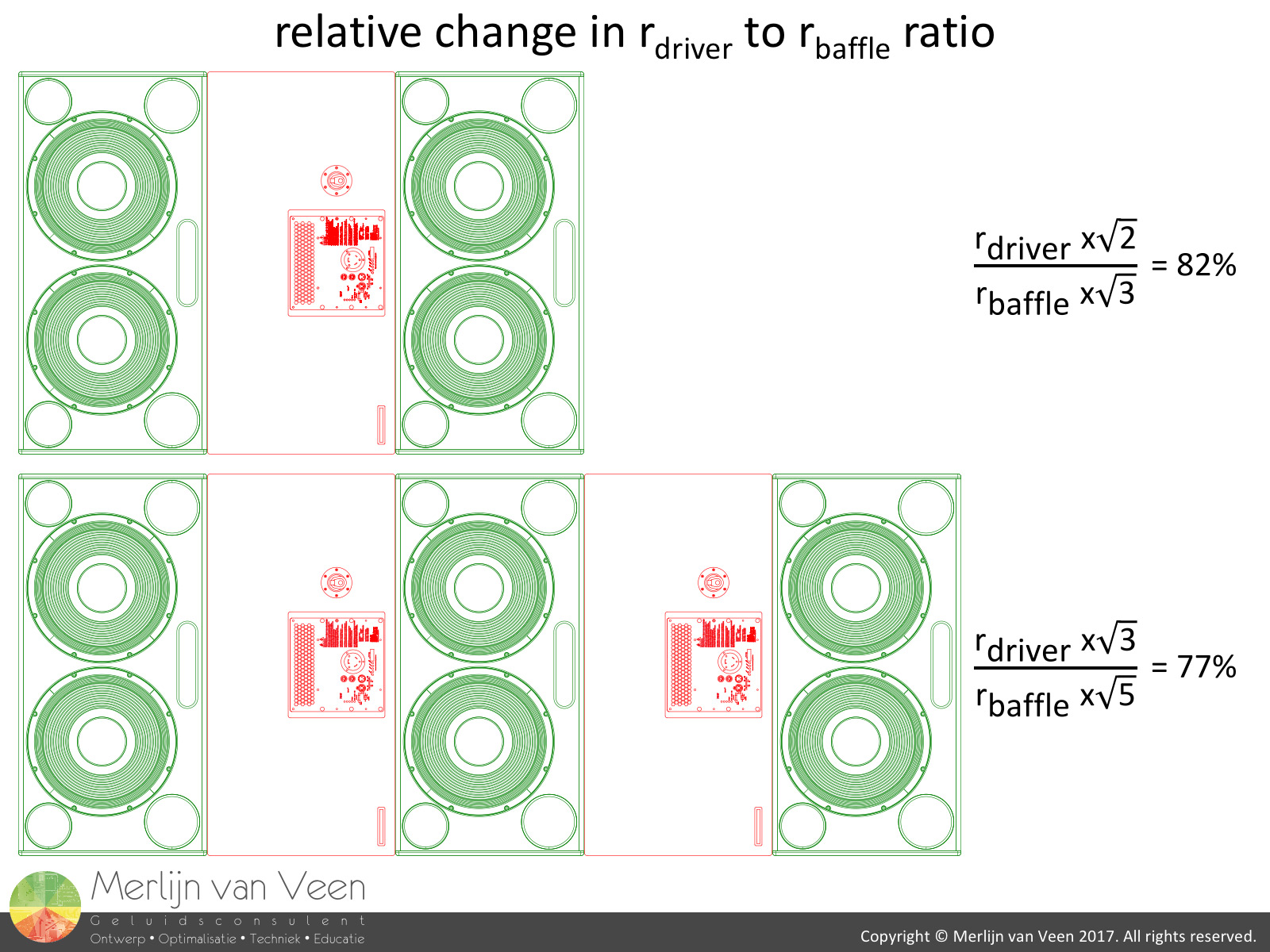 figure 8Figure 8 shows that the relative ratio of rdriver to rbaffle decreases when the array becomes bigger compared to a single speaker where radius is derived from area as if it were a perfect circular disk.
This decreasing ratio (x-axis figure 7) propels the acoustic center outwards, away from the driver (on axis).
Contrary, when the array becomes bigger, the (enclosure) depth remains constant but the effective baffle radius increases. Compared to a single speaker, the relative ratio of depth to rbaffle decreases and the acoustic center moves closer (y-axis figure 7) to the cabinet in the opposite direction. A push-pull situation.
The multiplier value shown along the z-axis shown in figure 7 remains virtually constant over array array size but when applied to an also inherently larger baffle radius, the acoustic center will still move outwards which is consistent with my measurements.
You might be interested to know that the FBF still shows a similar but lesser progression (smaller array) in terms of relative phase offset as seen in this article.
So, breaking up the baffle for gradient (CSA) stacks and arrays not only restores the level imbalance but also the time offset. Bringing us close again to the "center of tranquility at the eye of the storm". The configuration becomes easier to predict based on the performance of a single subwoofer.
Like I said in Part I, the challenge becomes to determine the minimum required gap size for improved rejection without a noticeable increase in lobing.
Fellow instructors, with who I shared my preliminary findings, started experimenting with air gaps between adjacent enclosures as little as the size of a fist and report improved rejection.
My own observations during Part II seminars confirm this. I intend to further experiment with simple spacers between vertically stacked subwoofers and it might very well turn out that even the casters underneath a dolly or wheel board could prove advantageous.
Stay tuned!
Credits:
These field tests would not be possible without the support and help of the people and companies below. Thanks a million!!!
- Heijmans and The National Military Museum for allowing me onto their premises at the former air force base in Soesterberg (NL).
- Sound & Light Import who sponsored (including transportation) the loudspeakers, amplification and processing.
- Audio Electronics Mattijsen who sponsored the Rycote windshields.
- Timo Beckman, Tom de Haas, Dico ter Maten, Vince van Seggelen and Lieven Verzele for the heavy lifting and good company.
Special recognition goes to Dico ter Maten for driving the truck and making sure that all equipment was running and working as advertised.
 This article is also featured in the February 2018 issue of Live Sound International magazine.