 If loudspeakers could somehow magically occupy the same point in space, our work would be considerably less difficult. Unfortunately, actual, physical loudspeaker enclosures prohibit us from doing so, which is when "Shit hits the fans" (plural). Physical displacement between multiple loudspeakers is one of the prime challenges in sound system design.
I was inspired to write this article by Nathan Lively of Sound Design Live who featured the Sub Align calculator spreadsheet in his recent video. Thanks!
Many of the calculator spreadsheets I wrote, were basically personal learning curves which on their own, make for worthwhile exercises. Ironically, by the time you finish them, you typically no longer need them. That being said, I hope they serve you just as well as they serve me, and advance your insight and careers.
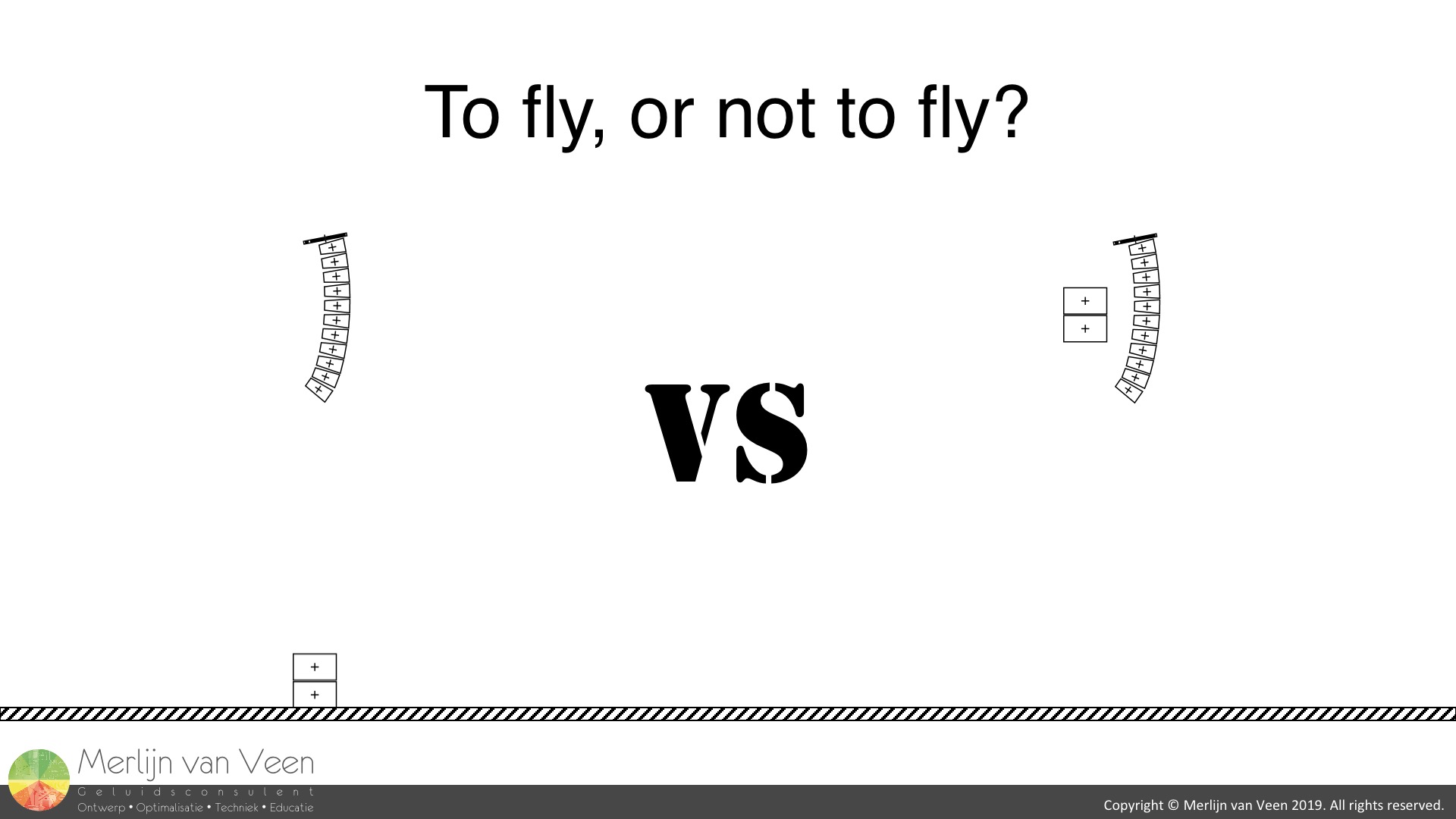
My personal big takeaway from Sub Align, as I was studying the subject, was when to abandon ground-stacked subwoofers and start considering co-locating the subwoofers with the (flown) main loudspeakers.
The Bipole
Two perfect omni-directional sources (monopoles), separated physically by a certain distance, form a bipole (same polarity) where the physical displacement between the sources translates into path differences experienced by surrounding spectators, which (at the speed of sound) translate into time offsets, which translate into frequency dependent phase offsets. The outcome, while highly predictable, can be thought of as coordinated chaos.
For a given frequency, at a given point in space, the two sources might interfere constructively (coupling) while simultaneously interfere destructively (uncoupling) at an entirely different point in space. In a two-dimensional plane this behavior manifests itself as an alternating pattern of power alleys (summation) and power valleys (cancellation).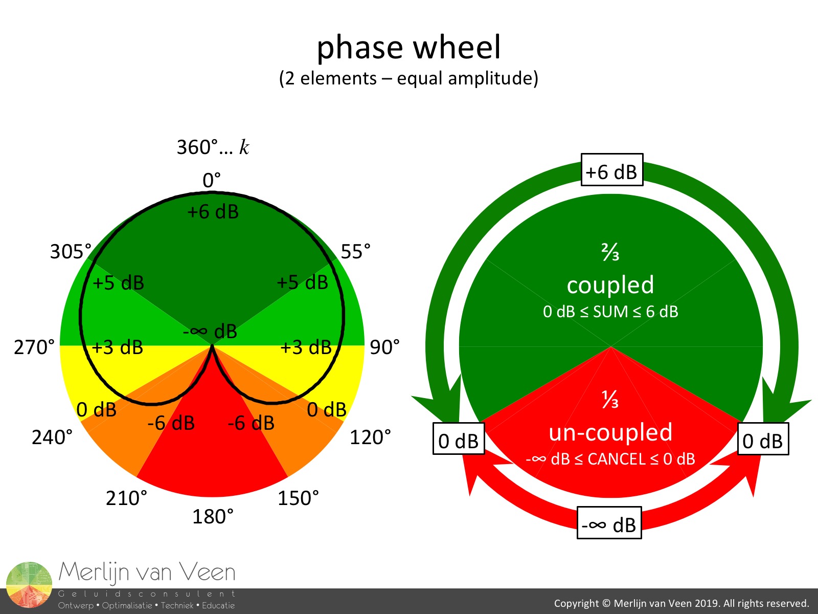 figure 1Coupling (summation) occurs every \(k\) cycles ±120° whereas uncoupling (cancellation) occurs every (\(k\)+0,5) cycles ±60° (figure 1).
Notice the two-thirds window of opportunity for coupling versus the one-third chance for uncoupling.
When in doubt, please consult the phase calculator spreadsheet or the chapter "Summation" which can be found in all three editions of Bob McCarthy's book "Sound System: Design and Optimization" (3rd edition now also available as e-book in Spanish).
Power Alleys and Valleys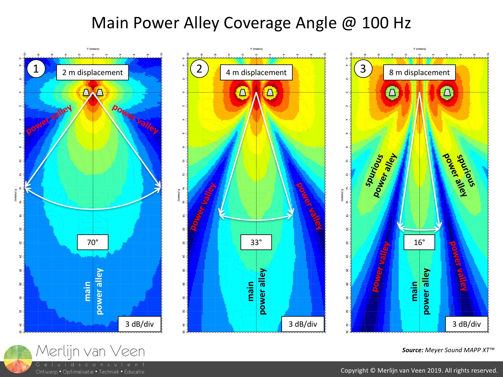 figure 2
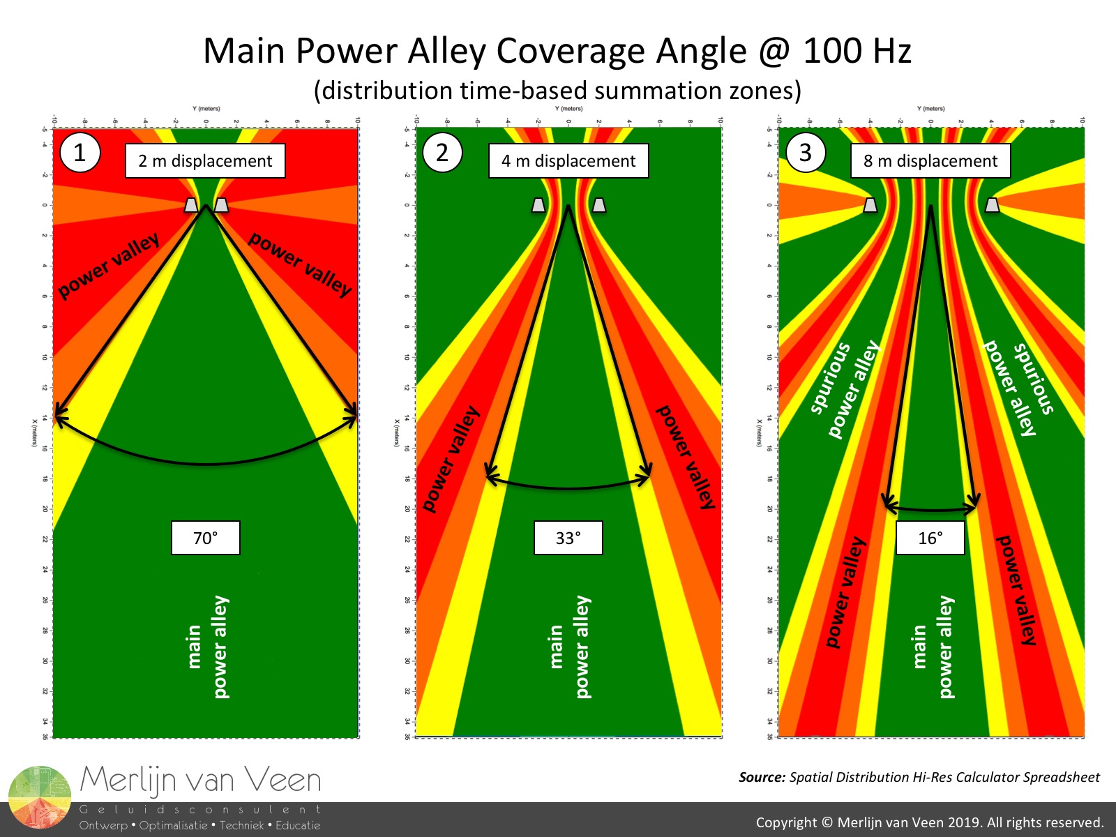 figure 3Figures 2.1 through 2.3 show two of these monopoles spaced 2, 4 and 8 meters apart respectively. Notice the previously mentioned alternating pattern of power alleys and valleys (6o6's "little blue rivers"). The power alleys occur when coupled whereas the valleys occur when uncoupled (figure 3).
Anyone who has worked outside with conventional LR subwoofers should be intimately familiar with this phenomenon. In the absence of a room, the contrast in SPL can be quite dramatic.
Indoors, the issue is typically somewhat alleviated because the power valleys are "filled" with late arriving, reverberant energy. Unfortunately, the latter typically also sounds feeble unlike the power alleys which sound firm.
Moving Target
The main central power alley lives in the median plan between the sources where you're always equidistant (ergo equitemporal and therefore coupled) to those sources. Unlike the other spurious power alleys, this main central power alley remains stationary over space, regardless of frequency, as long as you refrain from using Interaural Time Difference (IDT) stereo techniques. Its coverage angle however, is a function of the physical displacement between the sources as well as frequency.
Notice in figure 2, that the coverage angle of the main central power alley for the same frequency (100 Hz) changes with displacement. The coverage angle for a given frequency and displacement can be calculated using equation 1.
\begin{equation}\angle=2sin^{-1}\left(\frac{c}{3Df}\right)\end{equation}
Where \(\angle\) is the central power alley coverage angle in degrees, \(c\) is sound speed, \(D\) is displacement, and \(f\) is frequency in hertz.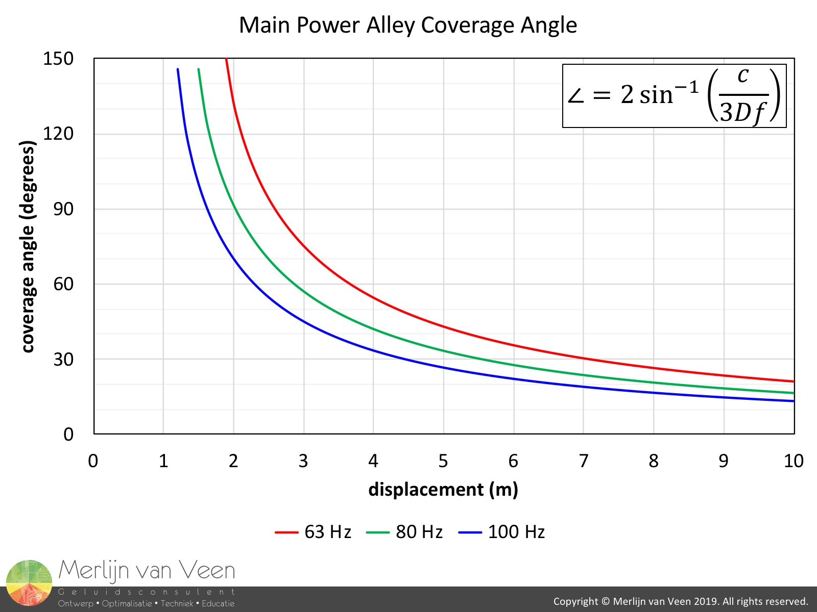 figure 4Equation 1 informs us that the main power alley's coverage angle narrows when \(D\) or \(f\) is increased, which is intuitively pleasing. Figure 4 shows three trends for 63 Hz, 80 Hz and 100 Hz respectively.
Ideally, all audience members reside within that main central power alley where time smearing is minimal. A futile exercise because the alley's coverage angle changes with frequency (equation 1) and typically doesn't offer enough room for all audience members; a problem inherent to LR subwoofers which most of us have made our peace with.
If this is unacceptable to you, alternative solutions such as (horizontal) subwoofer arrays might have your interest.
So, armed with a better understanding of power alleys and valleys in the horizontal plane, how does this apply to the vertical plane.
Warm-up Exercise
The Sub Align calculator spreadsheet shows you exactly where the main central power alley runs in the vertical plane (section view) using a checkerboard pattern. I've come to call this wedge-shaped checkerboard region the "cone-of-coupled-sound".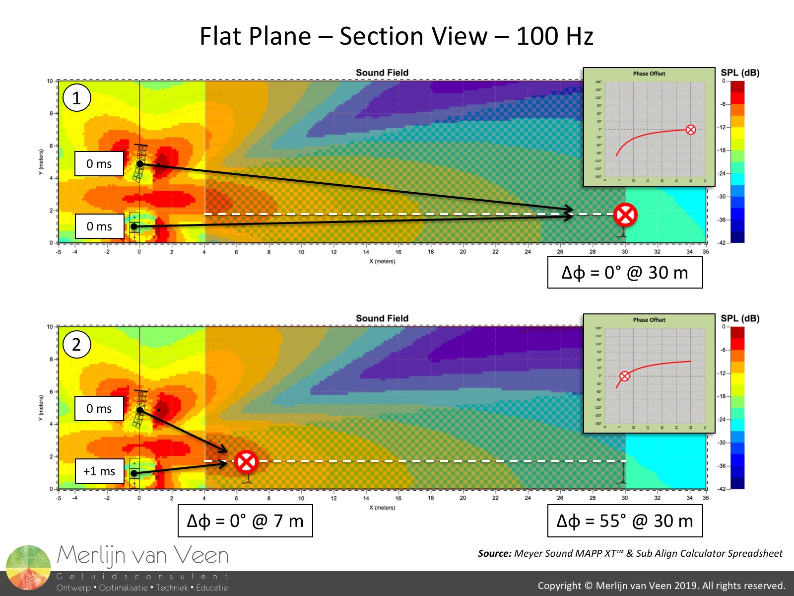 figure 5Figure 5 shows a very common scenario, e.g., a festival, with flown mains and ground-stacked subwoofers, where I've overlayed Sub Align's cone-of-coupled-sound. The cone-of-coupled-sound is always aiming at the position where mains and sub are time aligned.
Notice that in figure 5.1, the power alley's tip-of-the-flame is pointing towards the red cross at the last row (VTOP) which indicates the acoustical crossover (XO).
Despite the power alley's relatively narrow coverage angle (equation 1), its low angle of incidence makes it skim the audience at ear height, allowing it to cater the majority.
Conducting the main-to-subwoofer alignment at 7 meters distance (figure 5.2) where the subwoofers are leading (physically closer compared to mains), in stead of the last row (virtually equidistant), slightly increases the cone-of-coupled-sound's angle of incidence in exchange for a 55° phase offset at the last row which results in 1 dB less efficiency at that position (VTOP).
In this specific scenario, due to the geometry of the system setup in relation to the audience, either approach makes little to no difference, and I would conduct the alignment at FOH, provided it's sensibly located, to prevent the mixing guy or girl accidentally end up in a unforeseen null despite our best efforts.
Audience Elevation and Source Displacement matter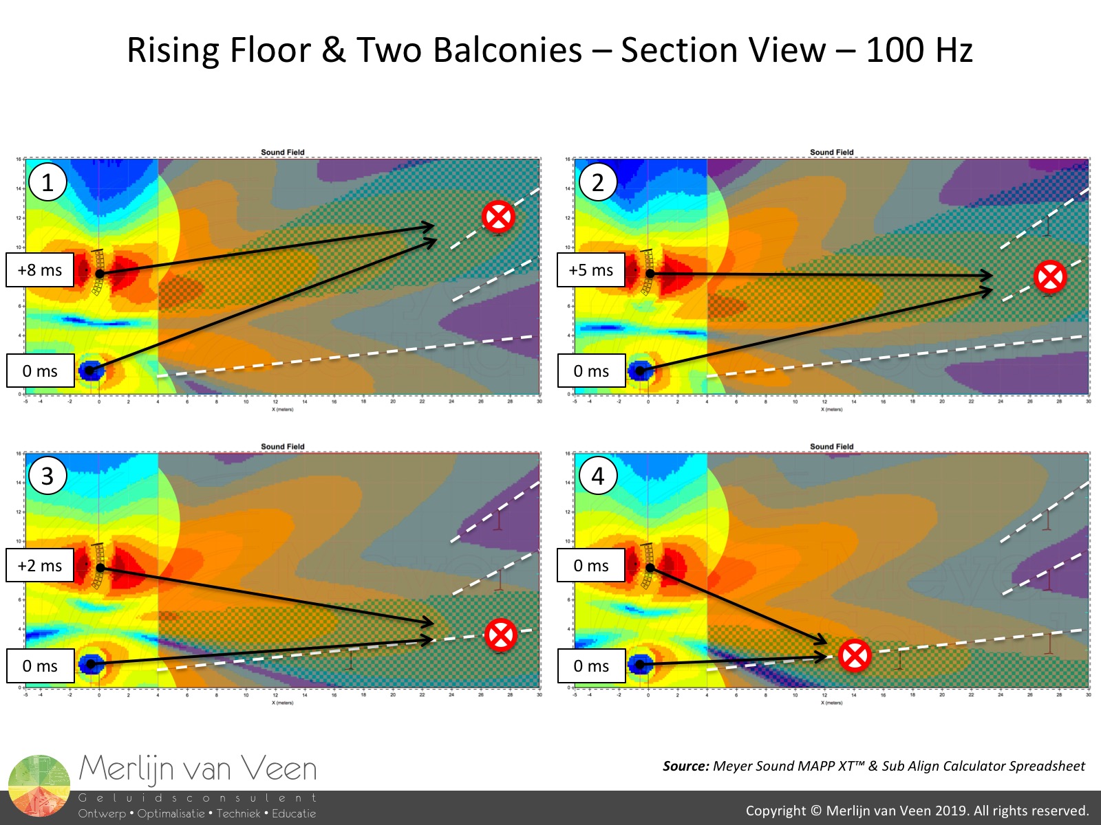 figure 6Figure 6 on the other hand shows a scenario where physical displacement between the flown mains and ground-stacked subwoofers becomes the bottleneck. I call it the game of hit-and-miss.
The position where main-to-subwoofer alignment is executed, determines the cone-of-coupled-sound's angle of incidence. The cone always touches down at the XO-position, but, because of its relatively narrow coverage angle, will hit certain parts of the audience while irrevocably over- or under-shooting the remainder. One of those adjacent power valleys could now underexpose an entire balcony! Regardless, the majority of the audience will not be catered throughout the crossover frequency range.
Under these restrictions, the cone-of-coupled-sound is too narrow and the majority of the audience won't end up in the main power alley. Its coverage angle needs to be increased and equation 1 informs me there are two ways to achieve that.
Lesser Solution
When physical displacement can't be changed, the (acoustical) crossover frequency needs to be lowered which will beam-spread the main power alley, capturing more of the audience.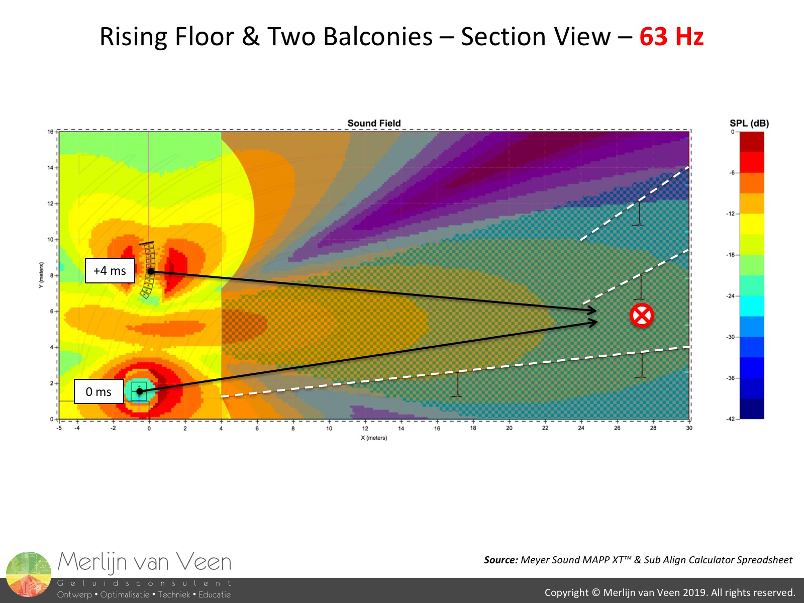 figure 7Figure 7 shows a cone-of-coupled-sound at 63 Hz which barely covers the audience majority. In practice, this would require the mains to run full-range (no HPF), all the way down to 80 Hz, possibly 63 Hz (depending on the size of the system), while low-passing the subwoofers at 80 Hz or 63 Hz respectively.
The subwoofer's (new) job description is now that of a low-frequency extension, reproducing only those frequencies which the mains can't. The trade-off is that mains are now doing the heavy lifting which makes this the least preferred solution. TANSTAAFL.
Better Solution figure 8Instead of lowering the crossover frequency, reduce the physical displacement which is the reason for all these issues to begin with.
Co-locating main and subwoofer in close proximity (figure 8), drastically improves the situation at the original, intended crossover frequency of 100 Hz.
As always, it depends. Choose your poison :-)
Addenda
For more information regarding the Sub Align calculator spreadsheet, please watch the following video.
Nathan Lively's video which inspired this article is shown below.