 "If a battle can't be won, don't fight it"
- Sun Tzu -
Whenever we experience too much of a particular frequency or frequency range, we're tempted to resort to equalization to resolve the situation. In this article I will demonstrate that the effectiveness of EQ relies entirely on the relative level separation from other sources.
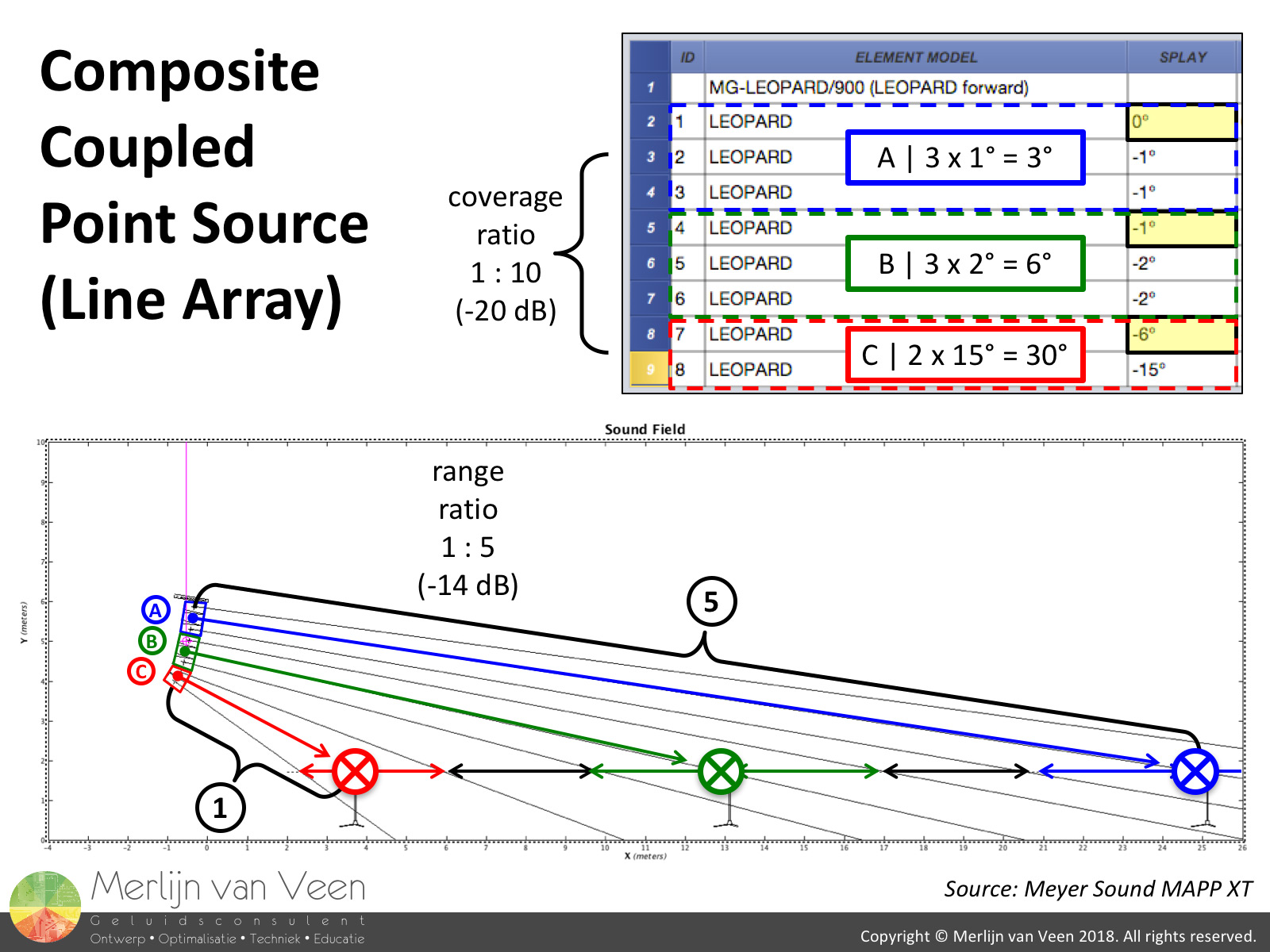 figure 1
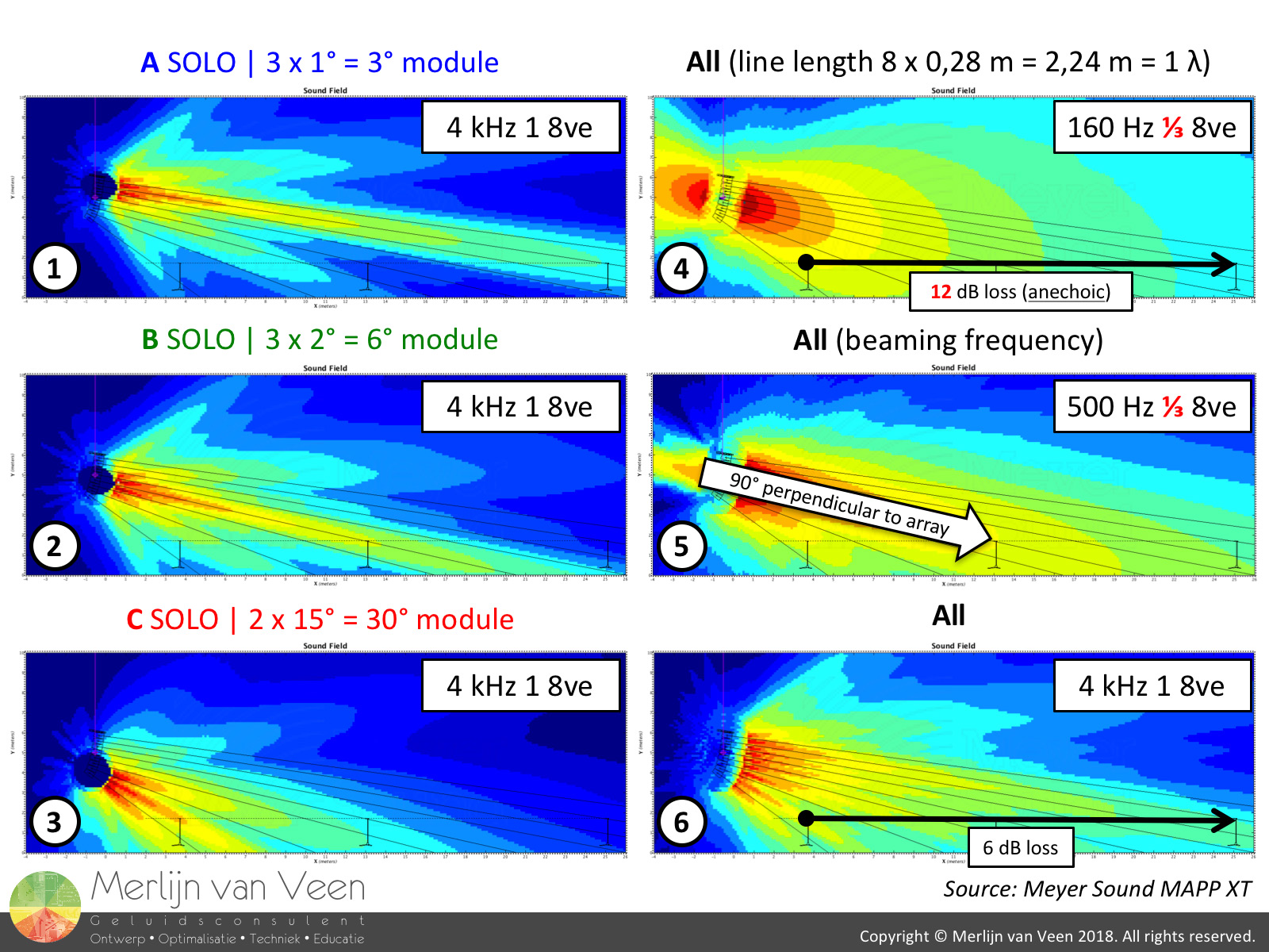 figure 2I design (figure 1) my line arrays as modular composite coupled point sources. Each individual module is effectively a perfect symmetrical arc.
I purposely set my splay angles to achieve a 6 dB level drop (figure 2, plot 6), front-to-back, in the frequency range where the waveguides become sole custodians (typically 2 kHz and up).
Mid- and high-frequencies approximate cylindrical wave behavior (3 dB per doubling distance) up to a certain distance and this way, the low frequencies, that are typically bound to spherical waves (6 dB per doubling distance) for finite-length arrays, have a chance of keeping up, once their loss rate has been decelerated by LF buildup / room gain (not shown in SPL plots).
Once the waveguides are sole custodians, designing line arrays is a relatively simple matter of "point-and-shoot" (amplitude steering). Unfortunately, at low frequencies, single line array elements are effectively omni-directional.
This renders them immune to rotation and therefor splay. Instead, the overall array geometry is the driving force (phase steering) behind low frequency control.
Ultimately, vertical pattern control is achieved by committee. It's a balancing act of "beam-narrowing" in the low-end versus "beam-spreading" in the high-end.
Vertical pattern control begins with roughly 72° (figure 2, plot 4) at the frequency whose wavelength matches the length of the array (nr. of speakers times their spacing).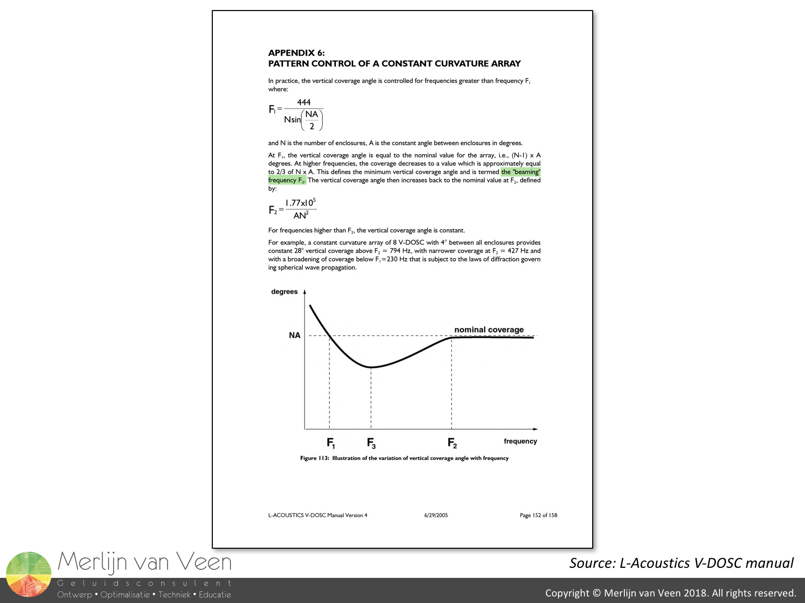 figure 3Conventional arrays however, tend to do a little too much of a good thing at the onset of pattern control. The French refer to this as the "beaming frequency" (figure 3) since the introduction of V-DOSC in 1992. For this particular array, the beaming frequency is approximately 500 Hz (figure 2, plot 5).
You can clearly see a concentrated beam of energy, perpendicular to the entire array, overshooting the beginning of the audience and making a nosedive before the end of coverage. This beam is typically about one-third narrower than the array's nominal coverage angle observed at higher frequencies.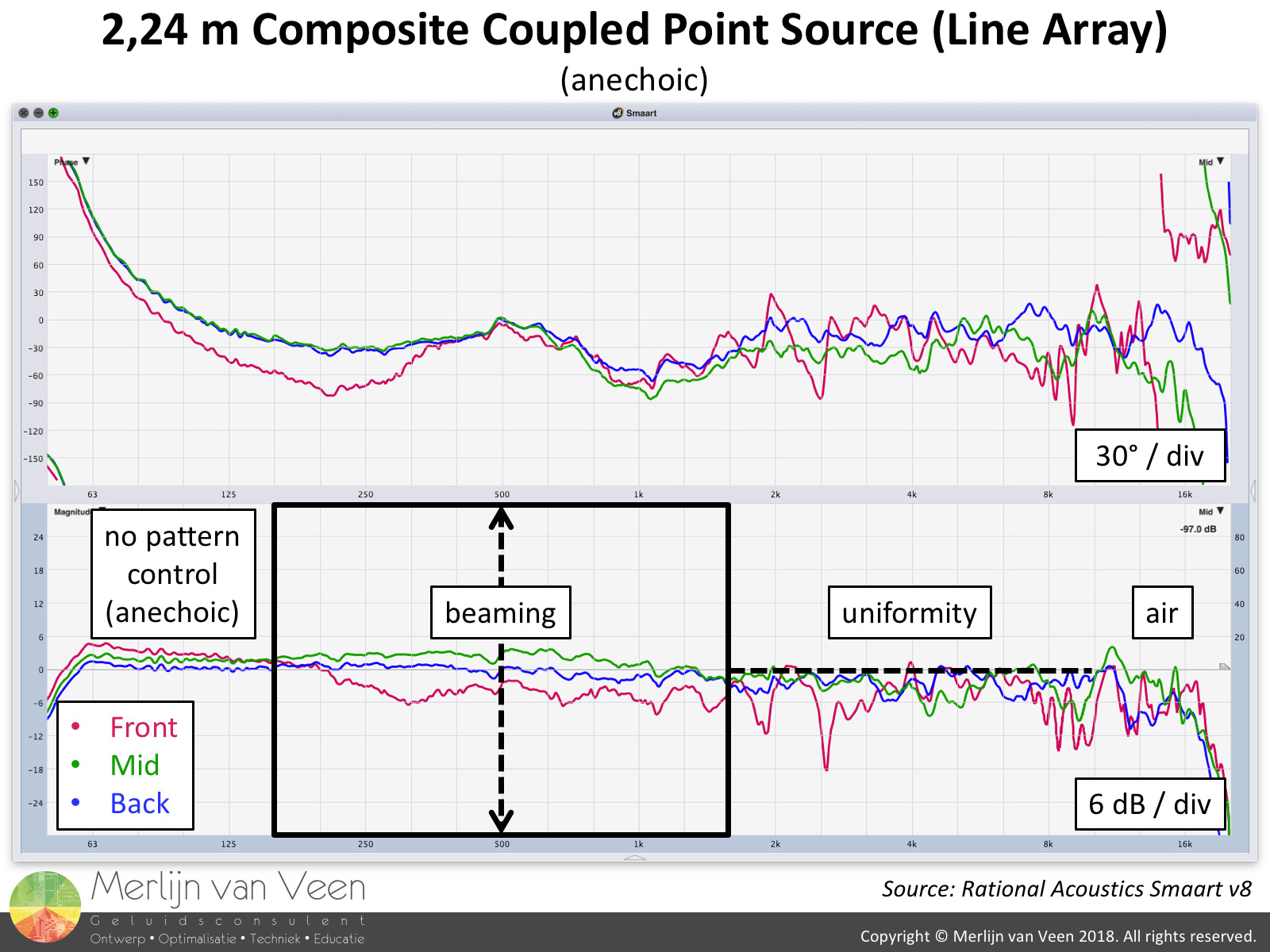 figure 4Figure 4 shows the "raw" anechoic system response (no processing). The traces have been aligned by means of an offset in order to assess uniformity.
In reality, frequencies below line length (160 Hz) will show matched responses with help of LF buildup / room gain.
Local HF attenuation caused by humidity, is proportional to distance and can easily be remedied with EQ. Provided, the array is subdivided in zones which the modular composite coupled point source happens to be.
In practice, this design approach will result in matched traces for half of the array's operational range in exchange for 6 dB of level variance front-to-back. Leaving only the decade centered around the beaming frequency which depends entirely on the geometry of the array.
In this specific frequency range, 6 dB of local tonal variance is observed. The bulk of this energy is concentrated in the area halfway through the audience. Suppose, you were to resort to EQ in attempt to even out the response over space by attenuating the offending frequencies in this part of the audience (B module) exclusively.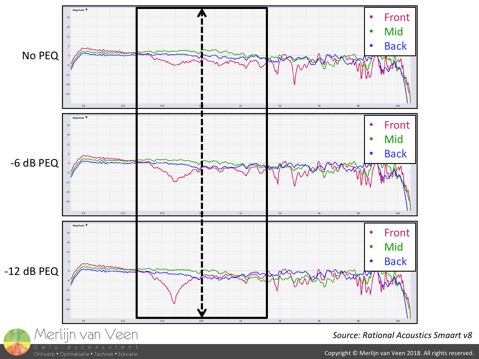 figure 5Figure 5 clearly shows that e.g. an octave-wide cut at 500 Hz in the B module has limited merit. It reduces the tonal variance to some extent but doesn't really address the concentrated energy halfway through the audience.
If anything, it appears to makes these frequencies go down in level globally, everywhere throughout the entire audience. In addition, we also observe the onset of a particularly nasty octave-wide cancellation at 315 Hz. So what's going on?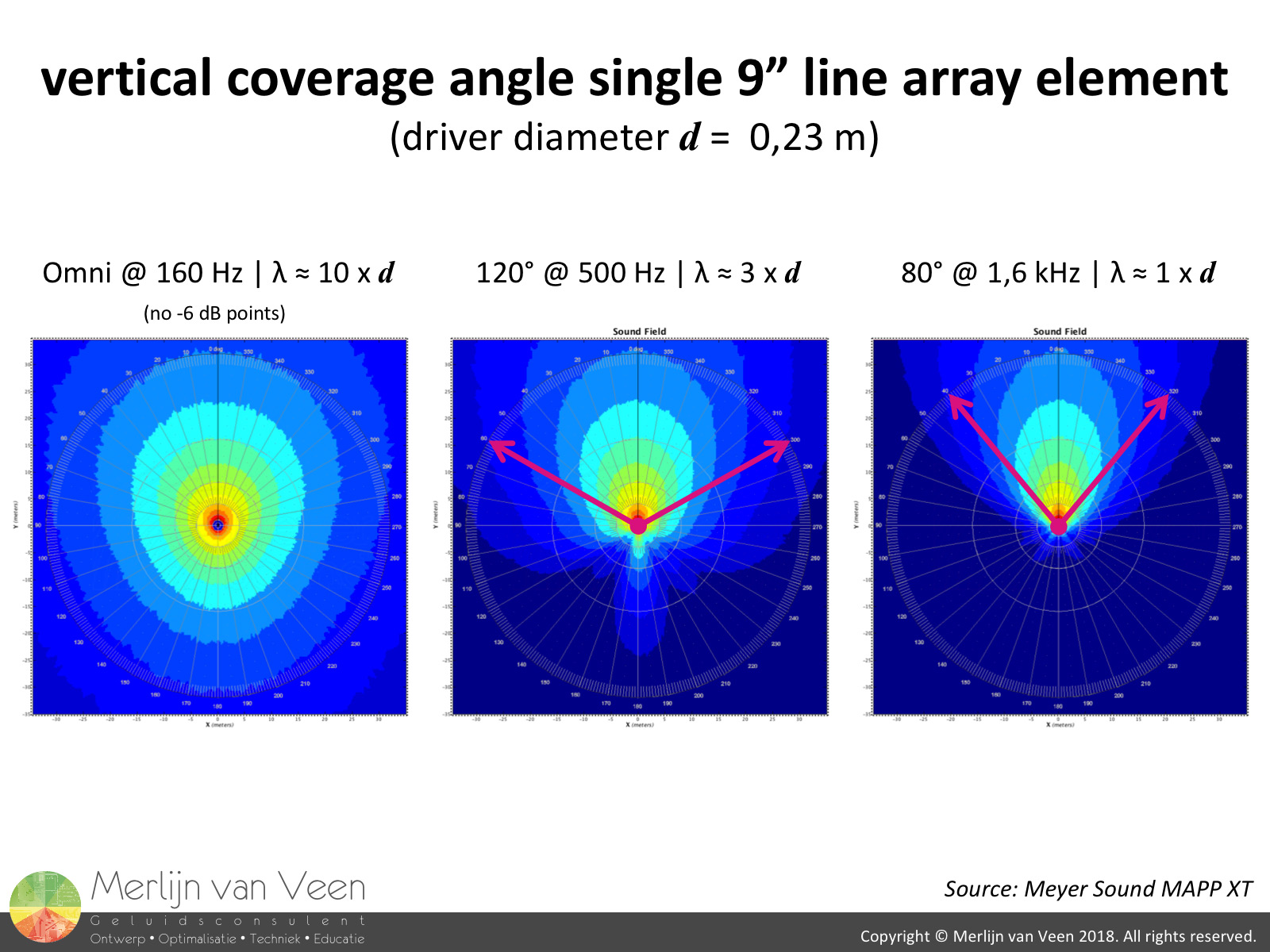 figure 6Single line array elements in the vertical plane, are so-called "Proportional Q" loudspeakers (figure 6). Their coverage angle is inversely proportional to frequency. From omni-directional in the low-end all the way to their nominal coverage angle, from as little as 5° to 15°, at 16 kHz.
There's a rule of thumb for piston drivers, responsible for the low-end, that states that at the frequency whose wavelength matches the driver diameter, the coverage angle will be roughly 90° (axisymmetric).
For this particular array, this implies that the entire "problem" region (160 Hz to 1,6 kHz), surrounding the beaming frequency, is joint custody of all speakers that each exhibit coverage angles of 80° or more. There's little to no isolation (level separation) from neighboring sources!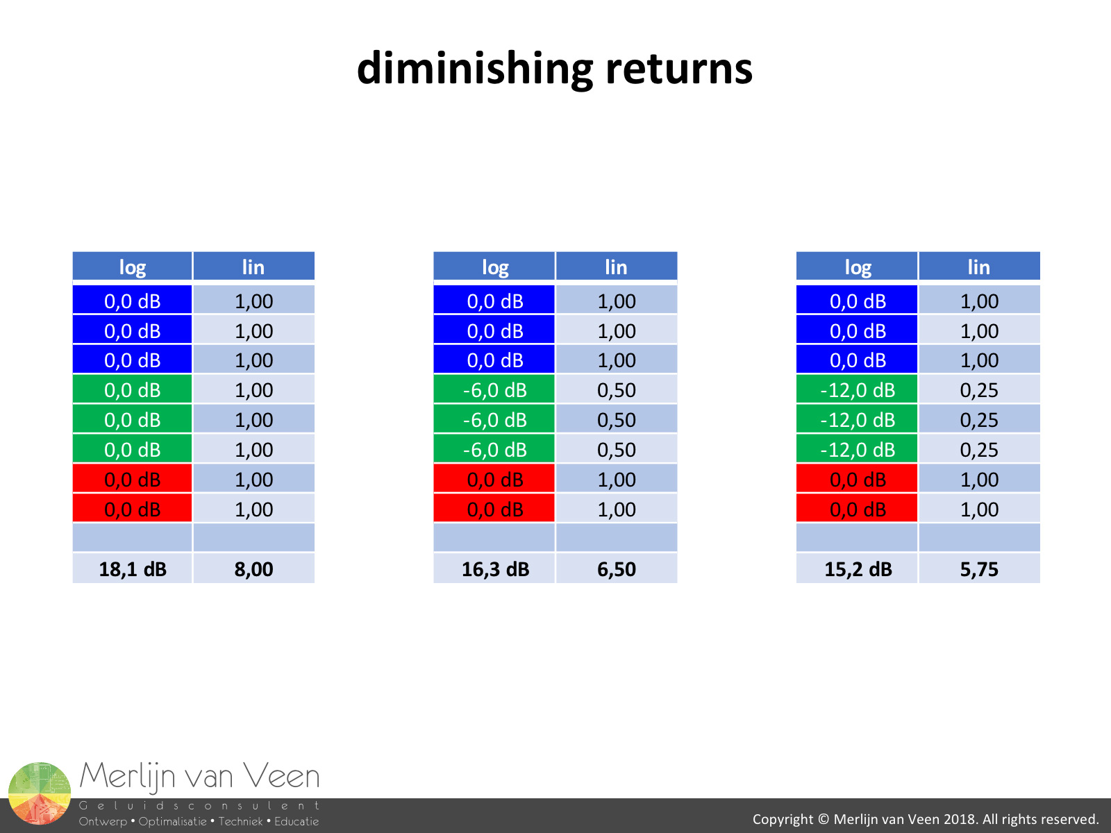 figure 7
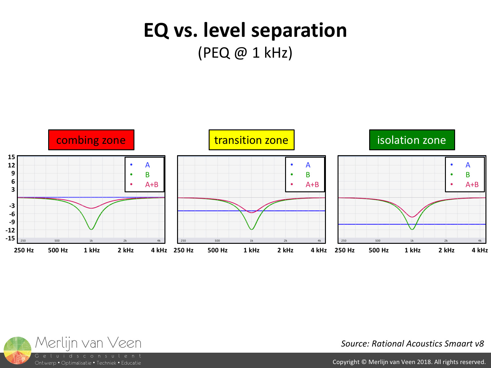 figure 8In the absence of isolation, EQ or level adjustment have limited merit. Lowering the level of a single module either by gain or EQ has primarily a global effect, affecting all spectators.
The tables in figure 7 show that attenuating the B module exclusively, does little to nothing for the grand total other than reducing overall headroom. Eliminating the B module all together, lowers the global level by five-eights or -4 dB at most!
However, if there's level separation, EQ will have a more profound effect. Figure 8 shows the effect of a notch when competing with another source. The red trace represents the sum of both signals. It's readily apparent that the notch becomes more effective when the other source looses market share.
This also applies very much to mixing! In the absence of crosstalk or "bleeding", ergo separation, EQ has a profound and tangible effect. The equalizer will feel very responsive. Contrary, Megabels of crosstalk will require more drastic measures that are typically accompanied by detrimental side effects. The latter very much applies to our array as well! figure 9Figure 9 shows what happens to the beam, should we decide to resort to EQ in the B module exclusively. It's readily apparent that attenuating the offending frequencies has no profound effect on the beamwidth. In fact, we observe the onset of a vertical interference pattern featuring power-alleys and valleys.
If not careful, it's ultimately as if the entire B module has been eliminated all together (figure 9, plot 4). Essentially turning a coupled point source into an uncoupled point source where the physical displacement has serious implications.
The uncontrolled spurious side-lobes seen in figure 9 could blow up in our face. What if they end up hitting specular surfaces e.g. a balcony face or rear wall, introducing discrete echos? The audience on a balcony in the custody of another system? Environmental pollution?
The principal precept in healthcare is: "First do no harm". Unfortunately, not everything can be simply remedied with a "level-band-aid" like EQ or gain. In this instance, that approach clearly has limited merit and is likely to cause more harm.
IF these speakers are virtually equally loud, because in this part of the spectrum they are still omni to hemispherical and fail to steer clear of each others territory (immune to rotation), they better arrive in TIME! This, is the root cause for this beaming phenomena.
The layout in figure 1 at the beginning of this article, clearly shows path differences. The difference between these trajectories translate into phase offsets and that's when "shit hits the fans" (plural - pun intended).
There's a time problem which requires a "time-band-aid" and the reason it's so audible is because the levels are matched!
For a real world example featuring actual measurement data please click here.
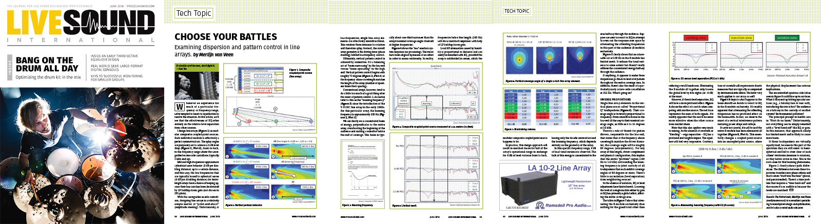 This article is also featured in the June 2018 issue of Live Sound International magazine.