
 In Part 2 of this series of articles, we discuss the trade-off for trying to achieve maximum coupling in front of a ground-stacked cardioid setup by reversing the bottom subwoofer.
At the end of Part 1, we concluded that in order to achieve the best possible coupling, even in the extreme near field, for a ground-stacked cardioid setup without the mandatory processing, it's best to reverse the bottom sub. We also saw that in the far field the sequence of front- and rear-facing speakers is of little concern.
In case you haven't read Part 1, I kindly request you to do so before continuing reading. Click here to read the article.
This article continues under the assumption that the reader is familiar with the inverted stack gradient setup (a.k.a. cardioid or CSA). If not, please consult the Subwoofer Array Designer manual or read Harry Olson's original AES publication from 1972.
Small format 3-element stack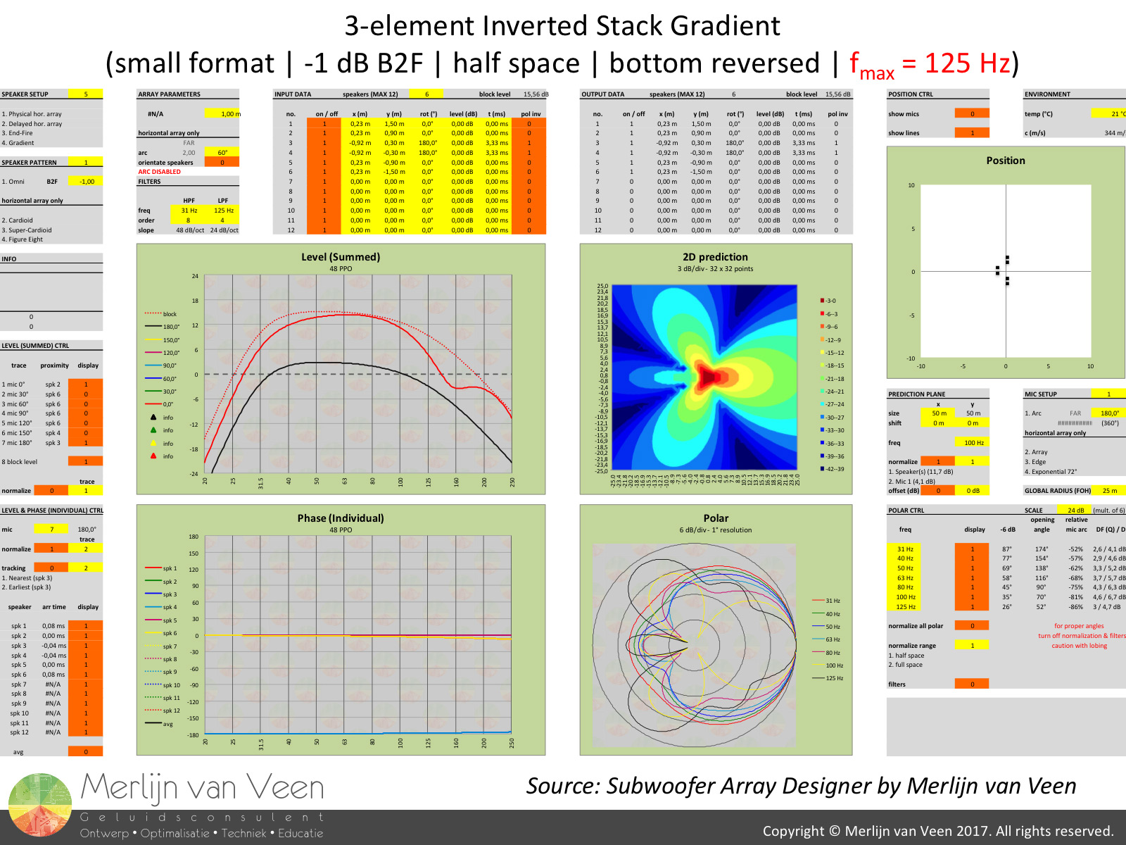 gallery 1
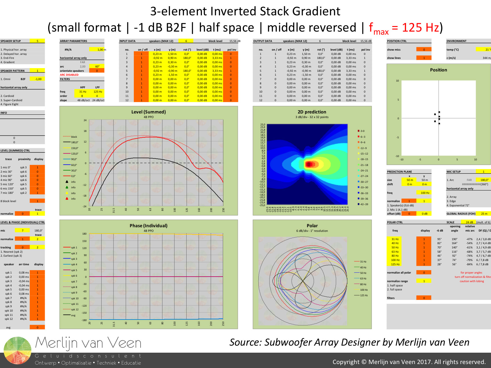
 Gallery 1 shows the results from Subwoofer Array Designer for a 3-element small format subwoofer setup. A single instance of the small format subwoofer is down by 1 dB in the back (180° OFFAX). Virtually omni-directional.
The reason you see 6 speakers instead of 3, is because 3 "mirror" images have been created to "mimic" the floor reflection. The observation distance is 25 m (75 ft) and for a typical setup like this, the usable bandwidth lasts up to 125 Hz (-6 dB point) at most.
Notice how regardless of the front- and rear-facing sequence, the transfer functions in front (0° ONAX - red trace) and behind (180° OFFAX - black trace) the setup remain identical. The reason we don't see perfect cancellation is because the ratio of front- to rear-facing subwoofers introduces an absolute level offset. We're not level matched in the far field behind the setup, even though we're out of phase.
The polar plots on the other hand, differ quite much. Particularly in the "higher" frequency range, several spurious side lobes can be seen. 100 Hz and 125 Hz have become quite the moving targets and environmental noise pollution or a clean stage come to mind.
Large format 3-element stack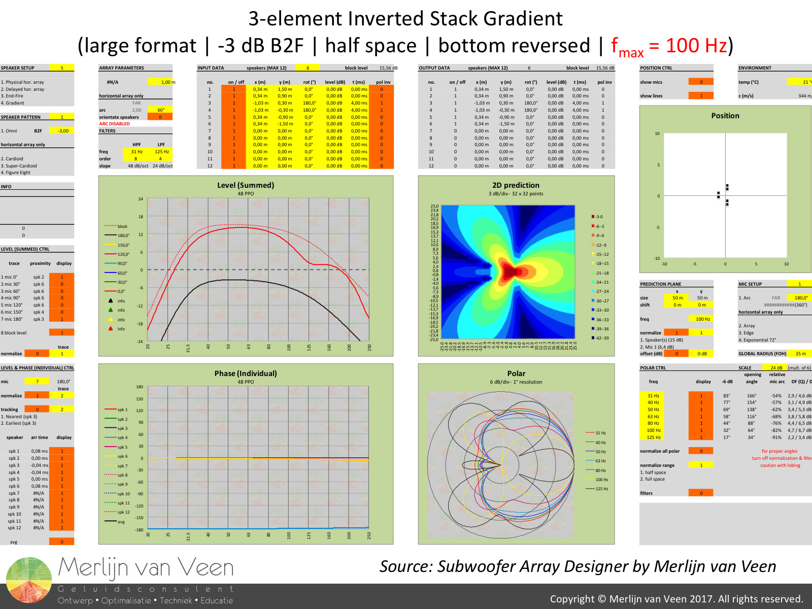 gallery 2
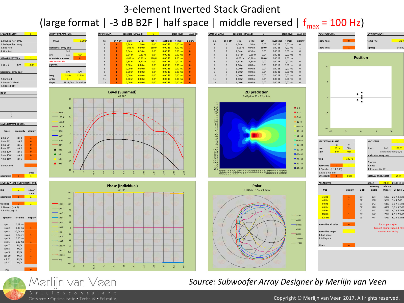
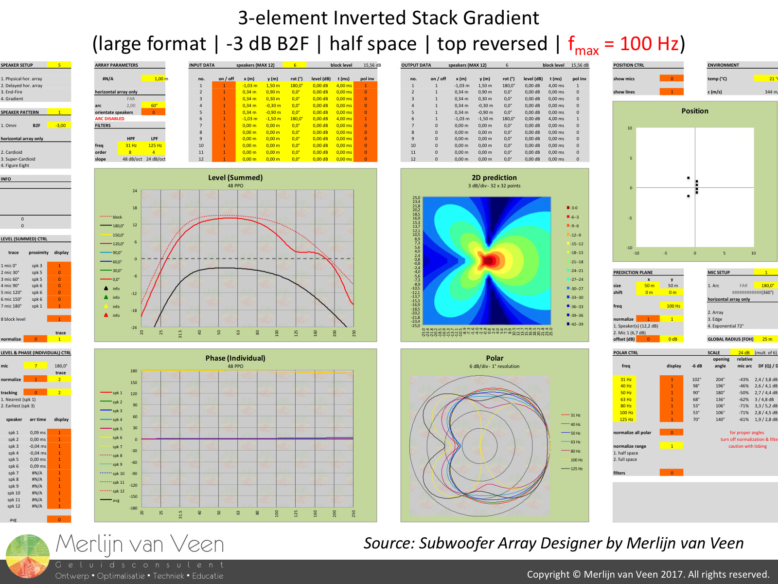 Gallery 2 shows a similar experiment for a 3-element large format subwoofer setup. A single instance of the large format subwoofer is down by 3 dB in the back (180° OFFAX). The usable bandwidth for a typical setup like this usually lasts up to 100 Hz (-6 dB point) at most.
Again, regardless of the front- and rear-facing sequence, the transfer functions in front and behind the setup remain identical. We observe better cancellation because the same ratio of front- to rear-facing subwoofers in combination with the inherent polar plot of the large format subwoofer, introduces a smaller level offset. The levels between front- and rear-facing speakers in the far field are approximating each other and cancellation increases.
The polar plots unfortunately differ considerably and even though I chose to show you 125 Hz, I would like to remind you that for a large format subwoofer, it's typically also out of bounds. 100 Hz however remains a moving target. So what about a 2-element setup?
Small format 2-element stack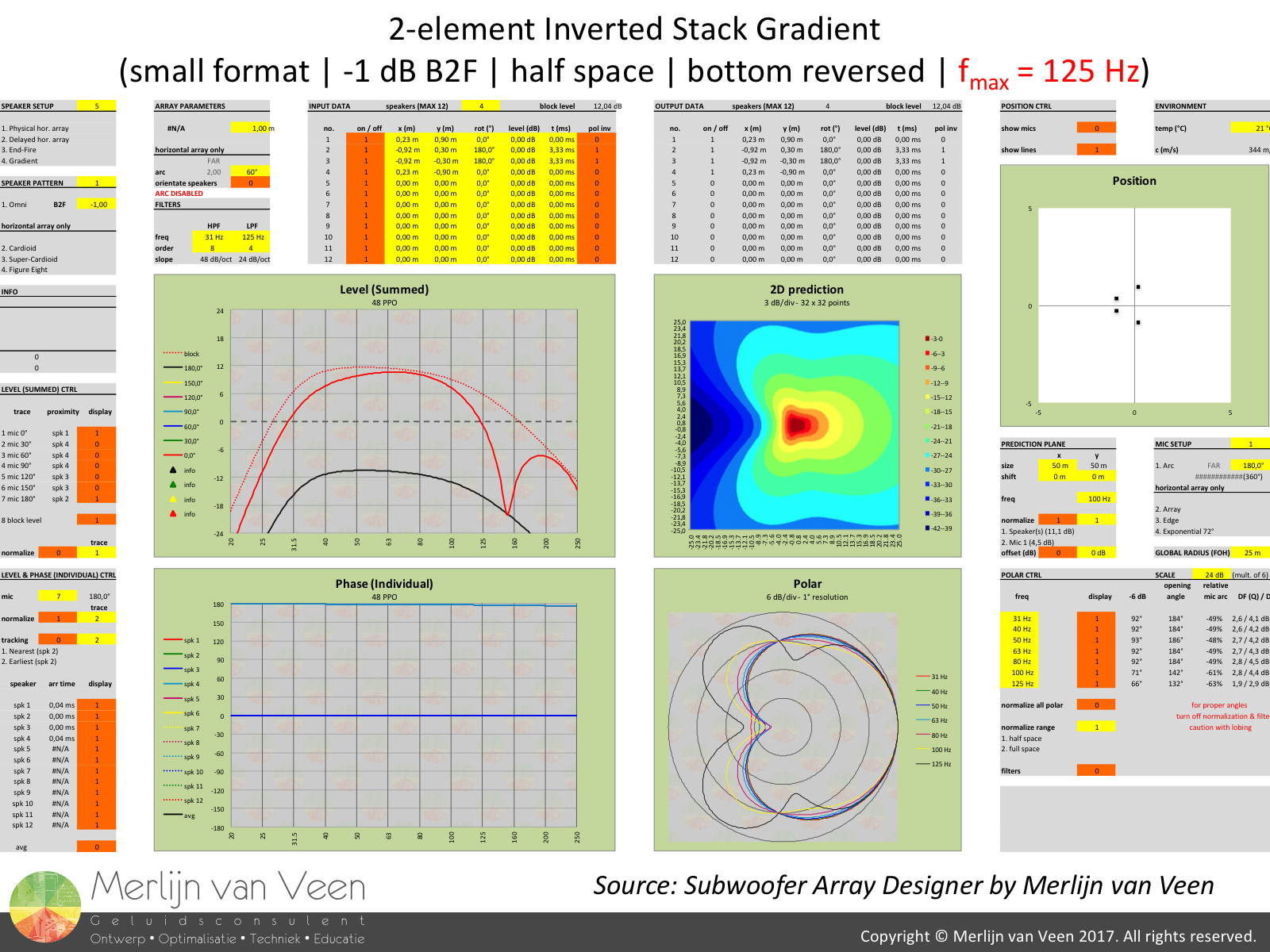 gallery 3
 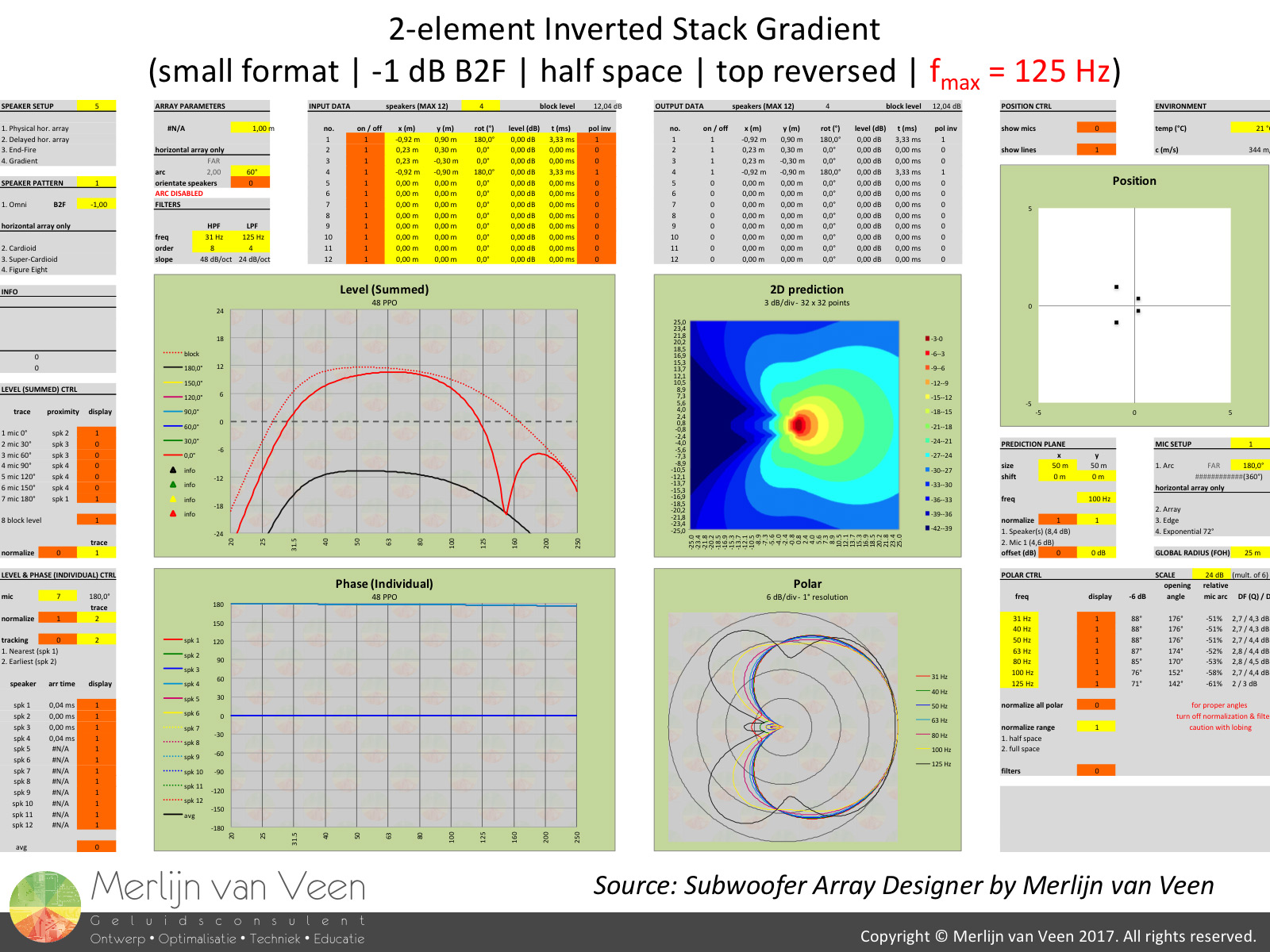 Gallery 3 shows a similar experiment for a 2-element small format subwoofer setup. Again, regardless of the front- and rear-facing sequence, the transfer functions in front and behind the setup remain identical.
We observe even better cancellation because this ratio of front- to rear-facing subwoofers (1 : 1) in combination with the inherent polar plot of the small format subwoofer which is virtually omni-directional, introduces the smallest level offset. The levels between front- and rear-facing speakers in the far field are of by 1 dB and cancellation is as good as it gets.
The polar plots differ very little because the psychical displacement with only 2 elements is relatively small in comparison to the wavelengths of interest. So what about the large format subwoofer?
Large format 2-element stack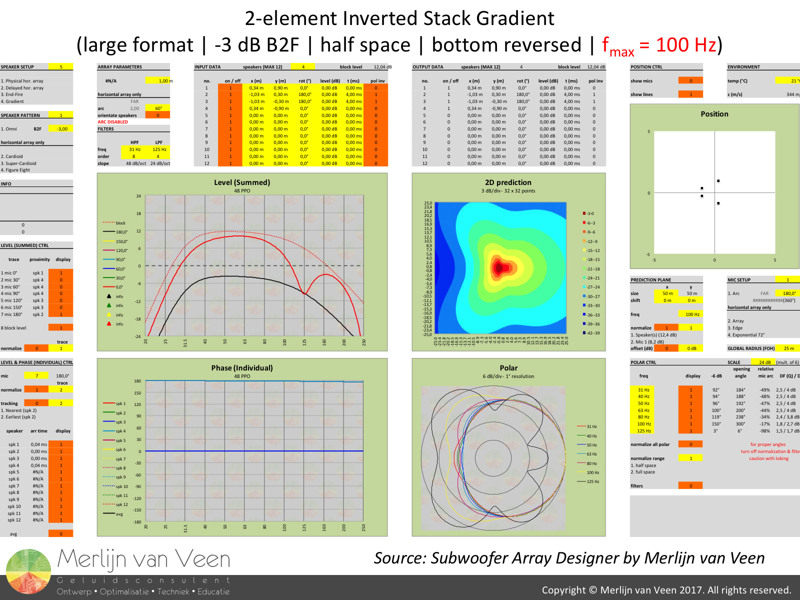 gallery 4
 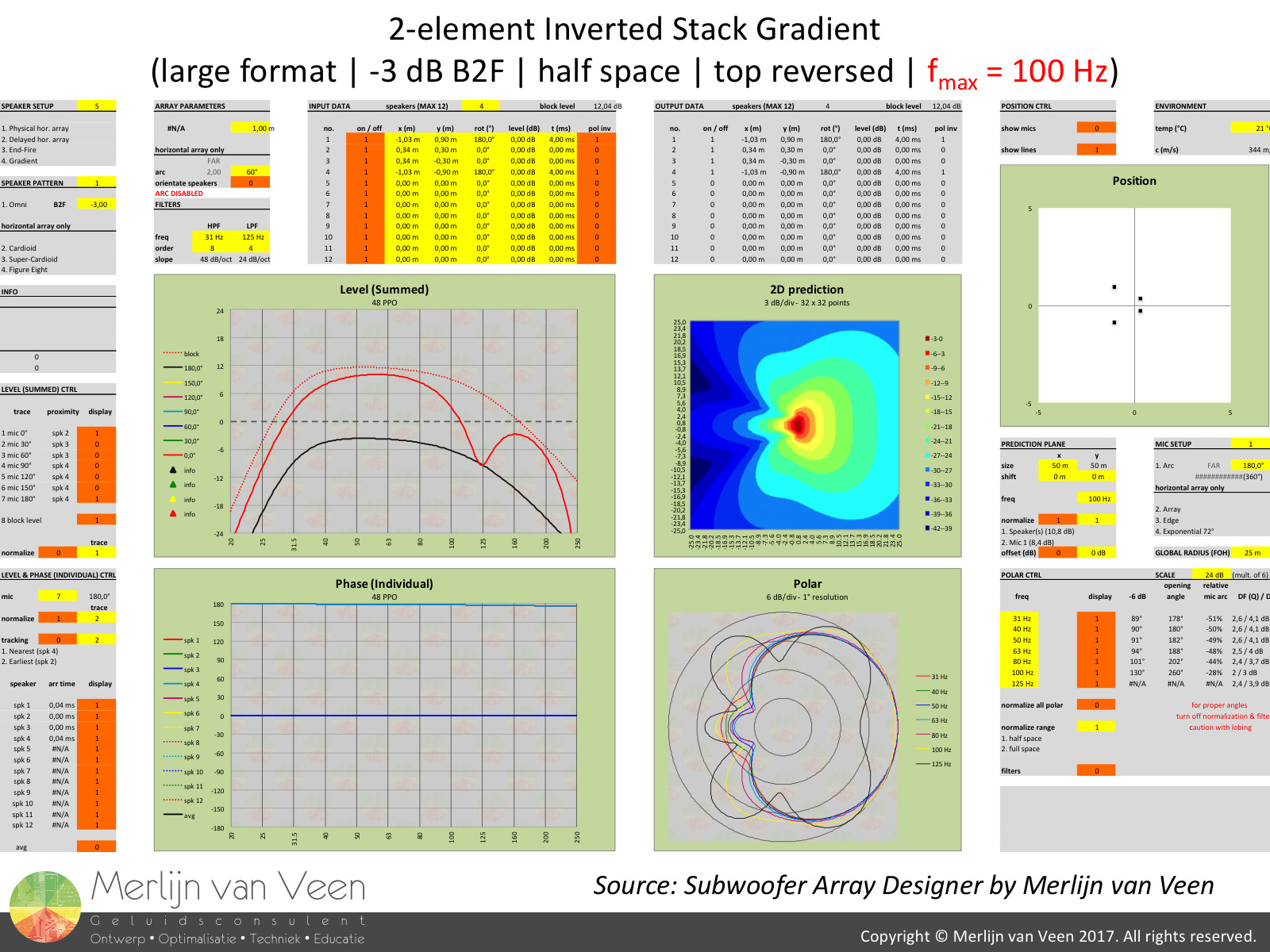 Gallery 4 shows a 2-element large format subwoofer setup. Again, regardless of the front- and rear-facing sequence, the transfer functions in front and behind the setup remain identical.
We observe reduced cancellation because the same ratio of front- to rear-facing subwoofers in combination with the inherent polar plot of the large format subwoofer, introduces a bigger absolute level offset. Apparently a 3-element small format stack and a 2-element large format stack produce similar amounts of cancellation in the far field?
The polar plots again differ very little because the psychical displacement with only 2 elements is relatively small in comparison to the wavelengths of interest and even though I chose to show you 125 Hz, I would like to remind you that for a large format subwoofer, it's typically also out of bounds. Time for an overview.
But before we do this, let's draw an intermediate conclusion. Apparently, the sequence of front- and rear-facing speakers or the format of the speaker makes no difference in the transfer functions at moderate distances and beyond both in front and behind the setup. This underscores our preliminary findings in Part 1.
Polar plot comparison figure 1
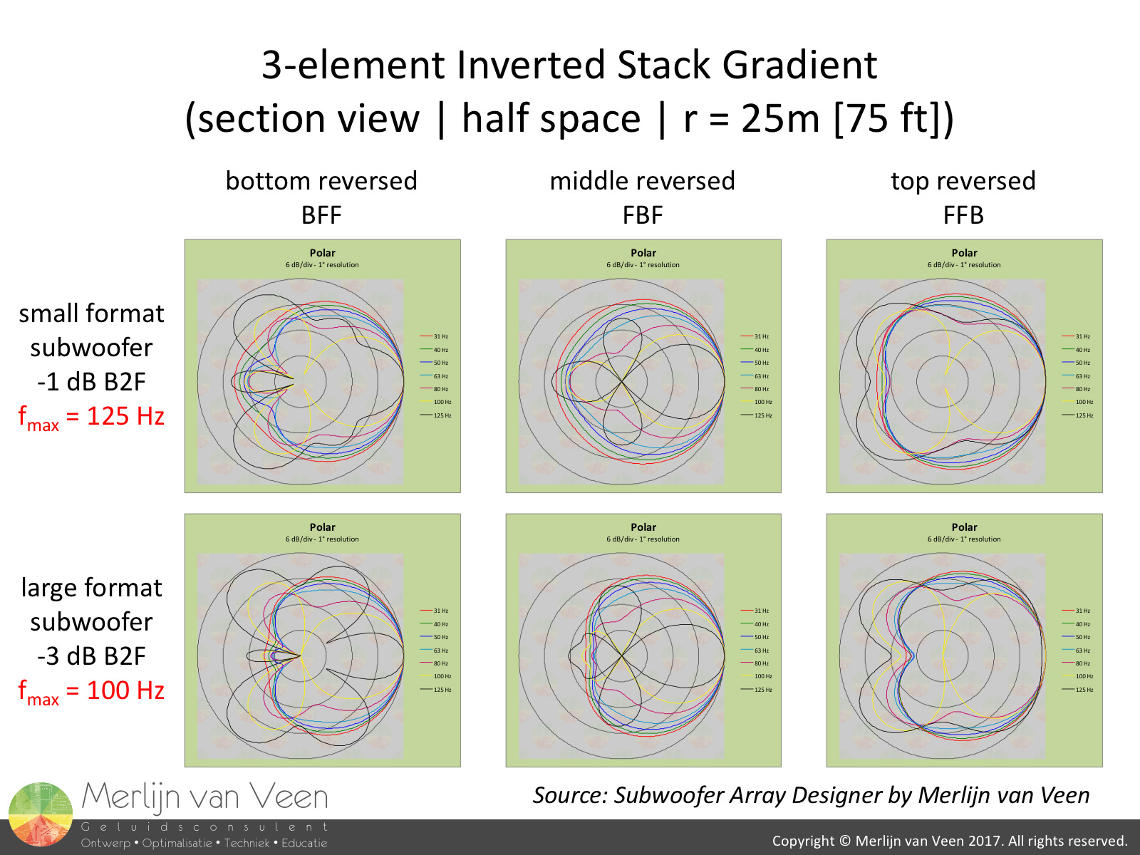 figure 2Figure 1 shows all polar plots for the 2-element stack both small and large format. With exception of 125 Hz which is out of bounds for the large format subwoofer anyway, the sequence of front- and rear-facing speakers makes little difference.
Figure 2 shows all polar plots for the 3-element stack both small and large format. Contrary to a 2-element stack, the sequence of front- and rear-facing speakers now produces severe spurious side lobes, because the physical displacement is now large in comparison to wavelength for the "higher" sub frequencies.
When we went from 2 to 3 speakers, we effectively made our "line" (including the "virtual" subs on the opposite side of the floor) 1.5 times longer. But the frequencies of interest kept the same wavelength and this bring us to the essence of this article which is "coordinated chaos".
The inverted stack gradient cardioid setup, as far as electronic processing is concerned, relies on two key concepts. First, electronic delay of the rear-facing speaker(s) by a value which approximates the depth of the enclosure (typically in the range from 3 to 5 ms). Second, a polarity inversion of the rear-facing speaker(s) in order for it to cancel the sound emitted to the back by the front-facing speaker(s).
The funny thing about electronic delay is that it always virtually "pushes" the speaker away, in the opposite direction, from the observer. It's not unidirectional, regardless from POV, like physical displacement.
We already saw that altering the sequence of front- and rear-facing speakers has little effect at moderate distances in front and behind the setup. So what about laterally (perpendicular to the floor)?
Lateral cancellation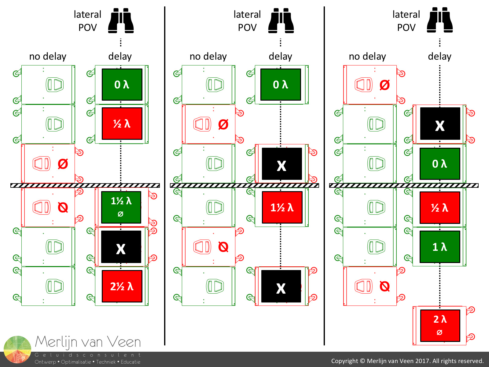 figure 3In figure 3 we observe 3-element stacks laterally. Since the electronic delay value typically equals one enclosure dimension, from a lateral POV all delayed speakers shift over by one "slot". Away from the observer.
The polarity inverted, rear-facing speakers that end up on top of front-facing speakers, effectively undo each other. This electronic delay is frequency independent and translates to a "virtual" physical offset. The cancellation will therefore be broadband.
When the bottom or top subwoofer is reversed this effectively eliminates only 2 out of 6 speakers, lowering maximum lateral potential summation by 20 * log10 (4 / 6) = -3.5 dB.
However, when the middle subwoofer is reversed, 4 out of 6 speakers are eliminated. Lowering maximum lateral potential summation by 20 * log10 (2 / 6) = -9.5 dB!
If we now set half a wavelength to one enclosure dimension, we can reason that for a particular frequency all "remaining" speakers will cancel each other out. Just count the number of green and red labels. This will be narrow-band cancellation.
This frequency occurs 1 octave up from the tuning frequency where maximum output occurs in front of the array. That's why all polar plots for the 3-element stacks (figure 2) show a lateral "null" somewhere around 100 Hz, regardless of the arrangement.
Apparently, reversing the middle subwoofer causes the most lateral cancellation, while making no difference in the front or in the back. So what about other directions?
Let's orbit animation 1If you look at animation 1, you'll get an impression of what happens when we circle around our stacks. The blue "crosses" represent the acoustic centers of the polarity inverted, rear-facing speakers, after we applied electronic delay with a value equal to one enclosure dimension. These centers are always "moving" away from the observer, like opposing forces.
Whenever a blue cross approaches a black cross (acoustic center front-facing speakers) within ± 1/3 revolution, they'll start to cancel each other towards the direction of the observer (opposite). With the middle subwoofer reversed this happens twice as often (potentially 6 dB more cancellation) in comparison to the other arrangements.
In or out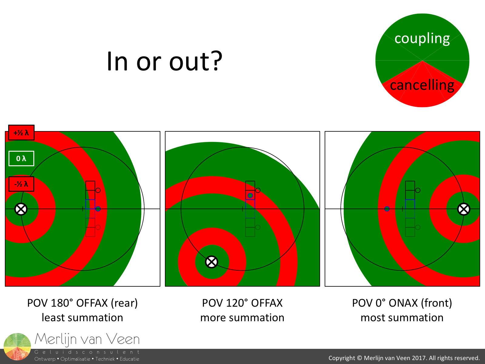 figure 4If we look at at a simplified version of the phase wheel (figure 4) and limit our options to either coupling or cancelling, we can see the odds favor summation 2 : 1.
If we co-locate subwoofers with a similar function (rear- or front-facing) we enable them to reach "critical mass".
If we represent each set of "twins" by a single acoustic center and circle the stack to e.g. 120° off axis, almost all speakers are summing. Remember, the rear-facing speakers are polarity inverted, so what looks like uncoupled is in actually coupled. That's why I filled the acoustic center of the rear-facing speakers with a green color.
The more green, the more summation.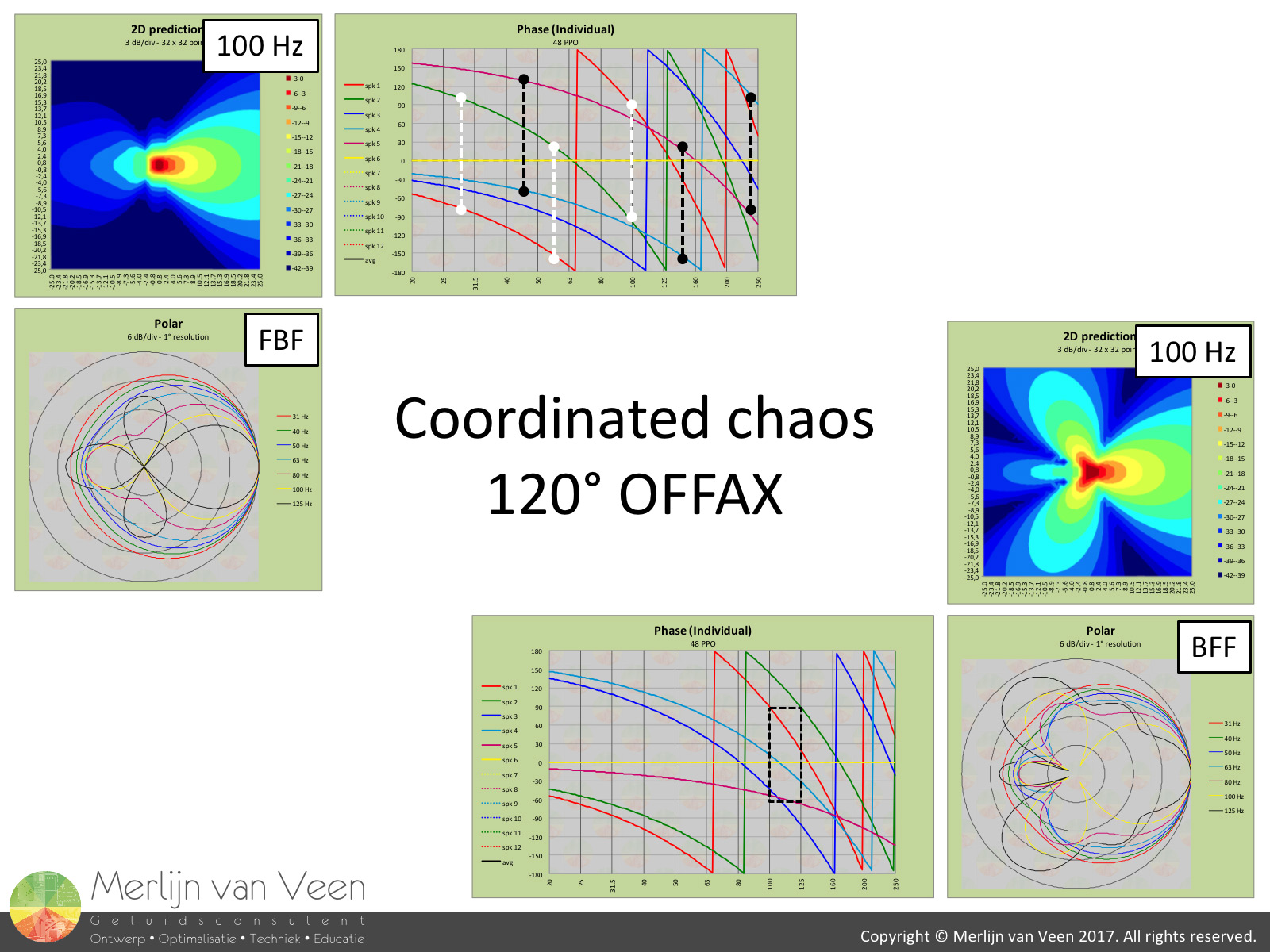 figure 5Figure 5 shows that for a Back Front Front arrangement, starting at 100 Hz, the majority of speakers are coupled within 120° or less.
However, if we "scatter" the speakers and prevent them from reaching "critical mass", we achieve coordinated chaos. Notice how in a FBF arrangement, 4 speakers for all frequencies are separated by 180°! animation 2Animation 2 shows half a revolution around the BFF stack.
Conclusion
For 2-element stacks the arrangement is of lesser concern.
Contrary, for 3-element stacks it's best to reverse the center sub and introduce coordinated chaos, knowing that the sequence will make no difference anyway at moderate distances and beyond, in front and behind the setup.
Apologies to the "SPL Preservation Society" for bursting your bubble. Reversing the bottom sub might result in better coupling in the near field but the trade-off is not negligible (figure 2).
Bonus question figure 6
 figure 7Using the table in figure 6, try to figure out why a FBFBF arrangement as shown in figure 7 would produce the best far field cancellation for a large format subwoofer. Keeping the backwash out of the territory of the opposite array, reducing interference :-)