 The most common complaint about gradient cardioid configurations is a lack of impact. This article hopefully sheds some light on both tonal and temporal mechanisms that arguably lead to this apparent but unwarranted sensation.
This article requires a good understanding of gradient cardioid configurations and phase aligning subwoofers to main speakers. Be sure to consult the S.A.D. manual for a more in-depth explanation of the former.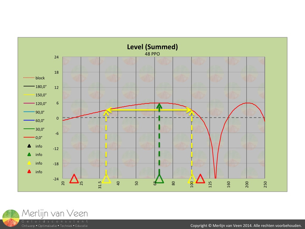 Figure 1
 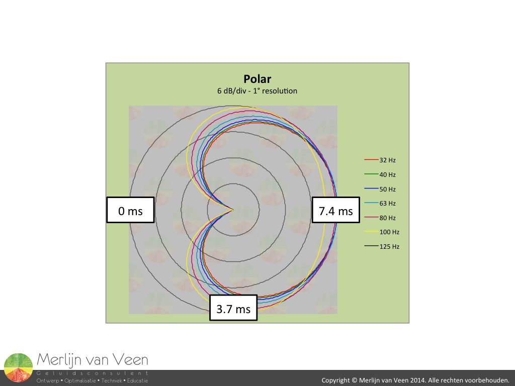 Figure 2The gradient cardioid configuration (in front of the array) behaves like a band-pass system which spans approx. 1,5 octaves between the half power or -3 dB points, regardless of the chosen spacing and corresponding delay (figure 1). To illustrate this article a configuration will be used that is optimized (temp = 21 °C) for usage from 35 Hz to 100 Hz with maximum summation at 68 Hz.
Lets start off by looking at the temporal effects or timing from a musical point of view first (figure 2). In front of the array the rear sub arrives 7.4 ms late to the party. Half of this is caused by physical displacement and the other half by means of electronic delay. This is as bad as it gets. When you move off axis equidistant to the array, the delay by physical displacement is gone once you find yourself perpendicluar (triangulation) to the array. Evidently behind the array there's no delay which is vital for the functioning of this particular approach.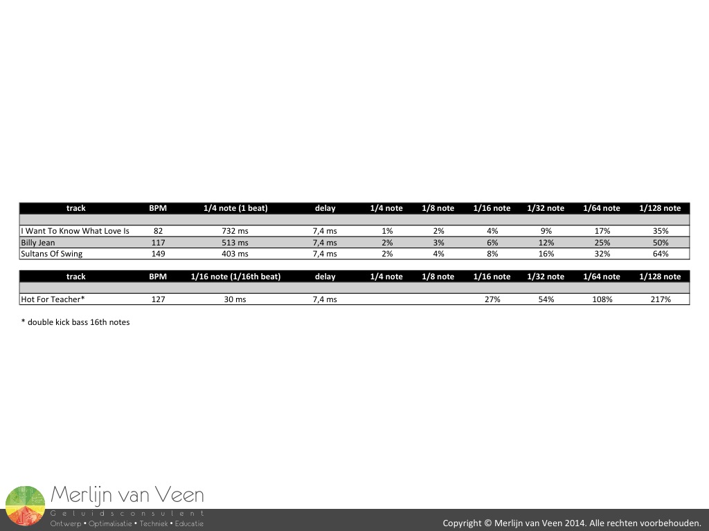 Figure 3What do these values mean in terms of musicality (figure 3)? I've chosen 4 well known tracks with tempi ranging from slightly slower than a walking pace (Andantino) to very fast and lively (Vivacissimo). Suppose a bass player plays a walking bass line (every beat a note) then the rear subwoofer would be off by as little as 2% for an up-tempo piece. Even when playing double time (2 notes every beat) the rear sub would be off by 4% at most. Only in extreme situations e.g. "Hot For Teacher" with double kick bass playing 16th notes (one, e, and, a, two, e, and, a, three, e, and, a, four, e, and, a), the rear sub arriving late by 27%, approx. 1/64th note, "could" become problematic.
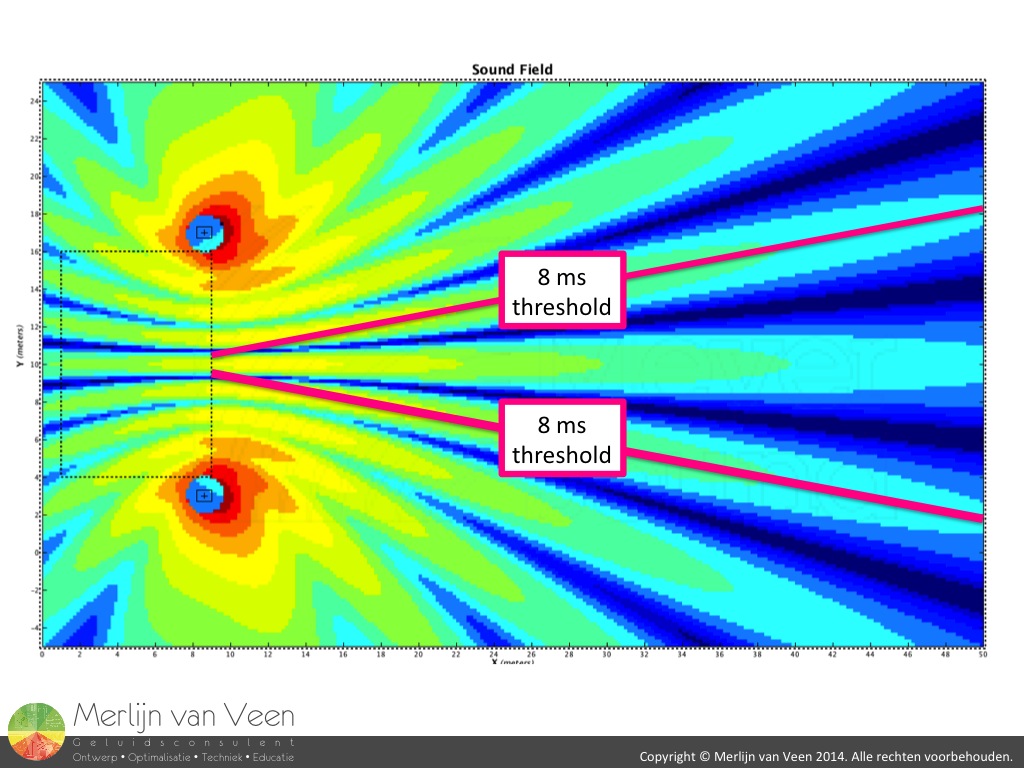 Figure 4To put things more into perspective, it takes less than 3 meters to experience timing offsets in excess of 8 ms in a regular stereo setup (figure 4). Be it at varying levels. A threshold that doesn't scale with venue size and this appears to be "acceptable" on more than one occasion.
Lets consider tonal implications. It's very important to take into consideration the individual subwoofer's inherit filter behavior. The vented enclosure is arguably the most commonly used subwoofer. By acoustical-mechanical design it exhibits 4th order HPF behavior where driver and port resonate. Add to this a secondary electronic HPF in series to prevent overexcursion and you'll end up with as much as 8th order (48 dB/oct) HPF behavior combined. For the purpose of this article I've conveniently chosen an 8th order Linkwitz-Riley HPF filter at 35 Hz, the lower limit (-3 dB) of our gradient configuration, with an easy to identify -6 dB point.
The upper frequency limit of the individual subwoofers used is predetermined by either manufacturer or user. The former can be to much of a good thing (e.g. a LPF below our intended bandwidth) or might require an additional LPF filter to provide the combined desired LPF needed for the gradient design. The latter allows us to place the LPF as we see fit. For the purpose of this article I've used both 2nd and 4th order Linkwitz-Riley LPF's at 100 Hz, the upper limit (-3 dB) of our configuration, with again an easy to identify -6 dB point.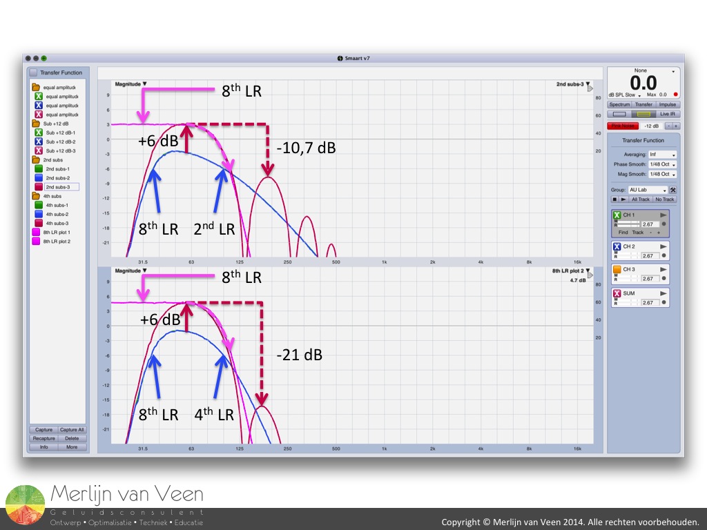 Figure 5The top plot in figure 5 shows the frontal response (red trace) of the gradient configuration using 2nd order low-passed speakers. The bottom plot shows the same design but with 4th order low-passed speakers. The blue and green (behind the blue trace) traces represent the individual speakers. Notice how the combined result, regardless of the LPF order used for the individual speakers, resembles 8th order LPF behavior (illustrated by the pink trace).
The first 10 dB of attenuation, needed to achieve isolation (frequency response ripple less than 6 dB) from the subwoofers, are the most important. This part of the combined response is illustrated by the pink dashed arrow and is in both scenarios near identical. The true importance of the chosen LPF's orders can be seen by the attenuation of the second peak in the combined response. In the first approach the amount of attenuation is barely 11 dB when using 2nd order LPF's. The second approach shows an increased reduction of 21 dB when using 4th order LPF's.
Based on this information it stands to reason to use a matching 8th order HPF filter for the main speaker (keeping the built-in HPF filter in mind), an unorthodox approach given the amount of phase shift and eventually increase in phase delay (group delay).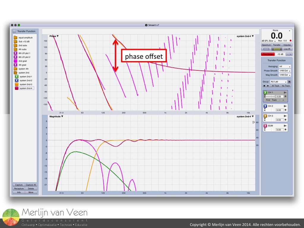 Figure 6Figure 6 illustrates the 2nd order low-passed subwoofer approach. The phase slopes of the gradient configuration (pink trace) and the main speaker (yellow trace) nicely align and summation is achieved throughout the crossover area. One octave up however, the response peak of the gradient configuration (barely isolated) sums out of phase and an octave wide response ripple can been seen. That being said this would be an acceptable solution.
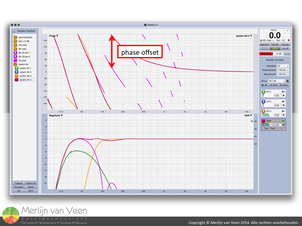 Figure 7Now lets look at the 4th order low-passed subwoofer approach (figure 7). Again the phase slopes align nicely and summation is achieved throughout the crossover area. Notice however the reduced response ripple one octave up by the reduced second peak of the gradient configuration.
Both approaches are valid and since the gradient configuration encourages us to use 8th order filters, we might as well go for the second solution with reduced response ripple. For those wondering, a lower order HPF for the main speaker (asymmetric crossover) would result in unmatched phase slopes leading to response ripple throughout the crossover area.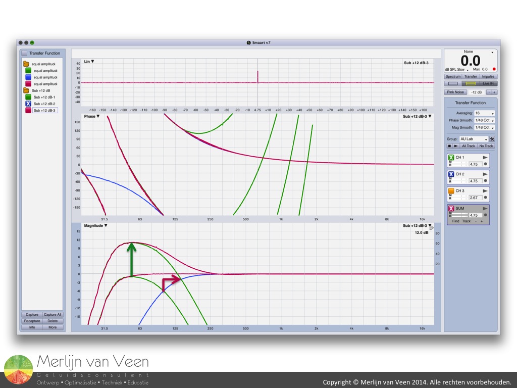 Figure 8The final exercise will focus on the consequences of LF emphasization by turning up the subwoofers (figure 8). I like LF emphasis in live sound as much as the next person and with conventional "omnidirectional" subwoofers this practice is relatively harmless as long as the initial phase alignment is maintained after the level adjustment. Evidently the acoustical crossover will shift up. About one half octave in this example. At the position in the audience where subwoofer and main speaker are now equally loud for the original crossover frequency, chances are, depending on relative time, that things got better OR worse. I recommend LF emphasization by low-shelf equalizing (keeping internal headroom of mixing desk and/or DSP in mind) instead. Like turning up the subwoofers, this will also result in more voltage being send to the subwoofers and maintain system integrity at the same time.
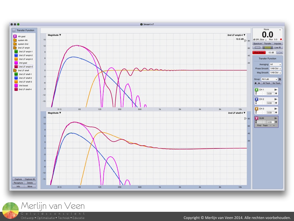 Figure 9Turning up the subwoofers in gradient designs for LF emphasization doesn't come without consequence and is most likely the foremost reason for the perceived lack of impact. The top plot in figure 9 shows severe cancellation around the second peak of the 2nd order low-passed gradient configuration after the level has been raised. The level of the second peak and the main speaker are identical but out of phase. It's a push pull situation and chances are you'll hear nothing but flapping cardboard. LF emphasization by low-shelf equalization (bottom plot figure 9) achieves the same effect whilst maintaining the relative relationship and amount of frequency response ripple.
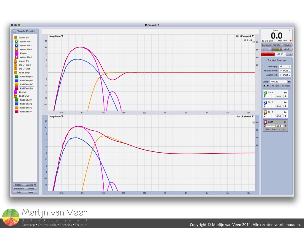 Figure 10For the 4th order low-passed gradient configuration (top plot figure 10), turning up the subwoofers is "more" benign due to reduced level of the second peak. But, LF emphasization by low-shelf equalization is evidently the more elegant solution (bottom plot figure 10).
To summarize, gradient cardioid configurations can be used to extent LF performance whilst maintaining impact. But only when the usable and unusable frequency ranges are respected. Relative levels between subwoofers and main speakers have to be kept close. LF emphasization requires other more upstream solutions.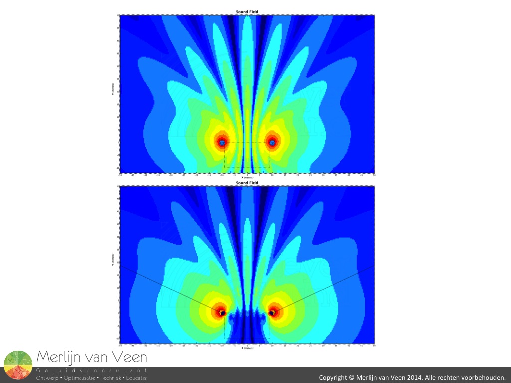 Figure 11Cardioid configurations inherently have directivity which allows you to orientate the sound in contrast to regular "omnidirectional" subwoofers that are immune to rotation (top plot figure 11). Power alleys can't be avoided, but the extent of comb filtering off center can be reduced by achieving isolation (bottom plot figure 10). Because of this better manageable interaction they allow for more complex system designs. Stage wash can be minimized and the house is being energized less in this part of the frequency spectrum. The latter will improve the direct to indirect sound ratio and increase critical distance.
To finish this article I've created a few audio fragments using the first 25 seconds of the royalty free track "Hang On Tight" from www.smartsound.com. These fragments have been processed in a DAW with exactly the same plug-ins that where used to create the transfer functions in Smaart v7. I strongly recommend you use a pair of headphones since we're focusing on the lower part of the audible spectrum which most likely won't be reproduced properly by your laptop speakers.
The first fragment is the unprocessed version and will serve as a reference. The second fragment is the 2nd order low-passed gradient configuration and to my ears the only audible difference is the small response ripple of -3 dB around 200 Hz. The third fragment is the 4th order low-passed gradient configuration and I have a hard time noticing any audible differences.
Fragments 4 through 6 are respectively a single "omni" sub with identical LPF behavior compared to the gradient configurations, the 2nd order low-passed gradient array and finally the 4th order low-passed gradient array. In contrast to the full-range fragments, the double timing caused by the rear sub is more audible. Especially the second more emphasized peak of the 2nd order low-passed configuration.