 Commissioned by Ampco-Flashlight Sales I was asked to optimize and tune the sound system in the small multipurpose hall of the new Atlas theater in Emmen (NL). The sound system was specified by Steven Kemland of Theateradvies comprising:
- 16 x d&b audiotechnik T10 line array speakers
- 4 x d&b audiotechnik Y-SUB cardioid subwoofers
Please continue reading for the complete process.
The hall features a retractable riser which is deployed most of the time with the exception of concerts. The challenge was to come up with a solution that caters both situations (retracted and deployed) and requires the least amount of adjustments made by the house engineers (both logistically and electronically).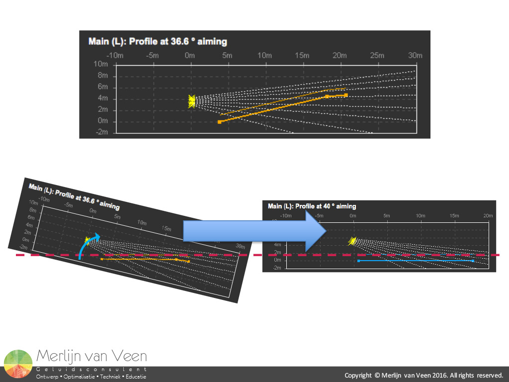 figure 1
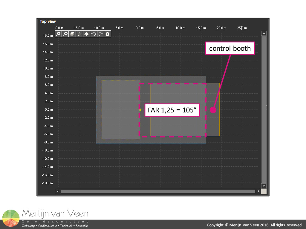 figure 2
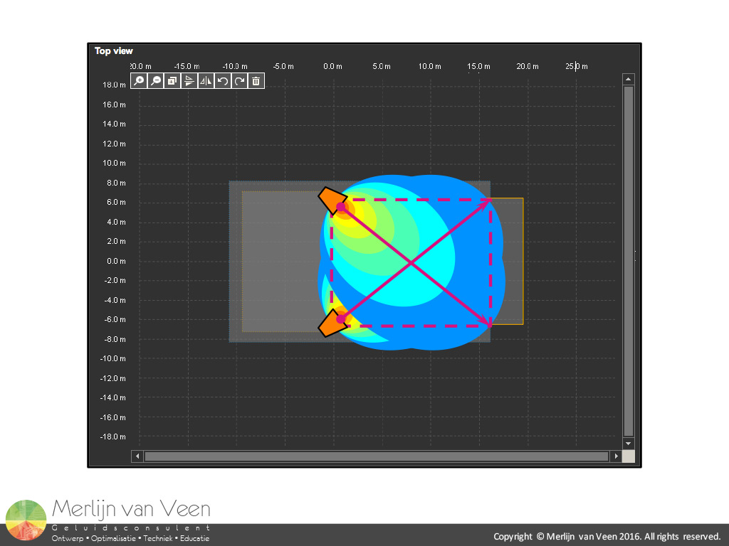 figure 3The riser exhibits a single continuous slope effectively tilting the hall by a 15° angle compared to the flat floor scenario (figure 1). I figured this simple geometry would allow me to get away with the same physically configured array which would then only need to be picked up at a different pick point and have the trim height adjusted accordingly to maintain the geometrical relationships. Also I needed to add an extra 50 cm trim height to account for a standing audience instead of seated audience. I started with the riser deployed scenario given the prevalence of this particular setup.
First thing I needed to do was to decide between a stereo and a dual-mono approach. The seating area in the plan view has a Forward Aspect Ratio of 1,25 (figure 2) and so does a single T10 line array loudspeaker with a horizontal nominal coverage angle of 105°. This opened up the way for true stereo perception for the majority of the audience.
Figure 3 shows the process of aiming through the geometrical center of the center towards the opposite corner. The icons show identical colors for the majority of the audience indicating matched levels between the left and right channels. A prerequisite for stereo perception. Some refer to this as cross-firing and there are even those who think the stereo image will flip because of this. Rest assured no stereo images were harmed during the aiming of this sound system.
Next I had to determine the trim height. I always try to go as low as is reasonably possible. The T10 allows for splay settings ranging from 1° to 15°, theoretically allowing me to get away with a 15:1 range ratio or 24 dB. Fortunately a more sensible solution presented itself. figure 4
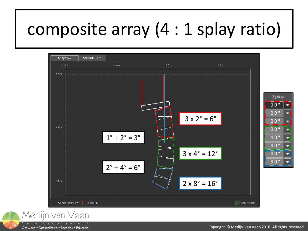 figure 5
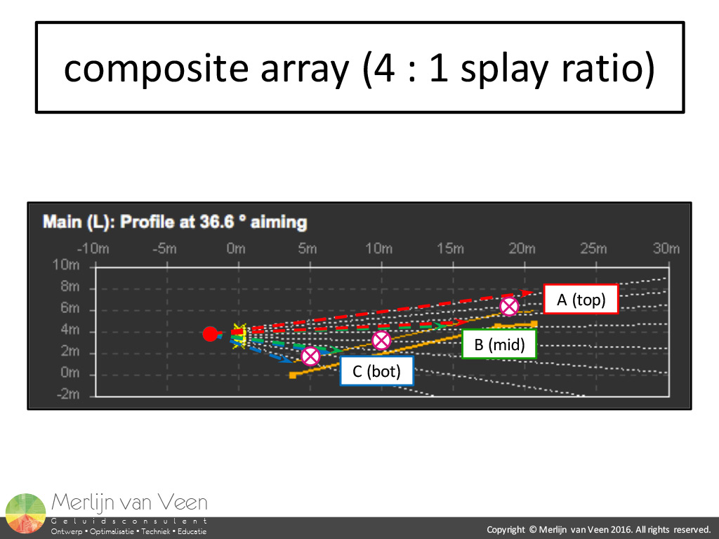 figure 6
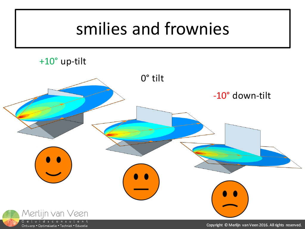 figure 7Figure 4 shows that if we divide the elevation difference front to back we're left with a modest 4:1 range ratio or 12 dB. From a sonic perspective point of view, this divides the vertical "distortion" in perception. With 8 speakers per side this is well within their capabilities. Determining the range ratio for a line array system requires some imagination. After all the virtual point of origin resides behind the actual array.
As for the actual splays, ideally the range ratio is reflected in the splay ratio as well. The values in figure 5 show a 4:1 splay ratio between the 2° splay used in the top and the 8° splay used in the bottom. Subdividing or "zoning" the array in my opinion is mandatory if you intend to solve local issues like level variance and different degrees of HF absorption by air. After all there are different amounts of air between the array and the front, middle and back of the audience respectively.
I go out of my way to make each subdivision of the complete composite line array symmetrical. In this particular example I ended up effectively with a single 6°, 12° and 16° speaker with easy identifiable on axis positions for the measurement microphones to verify the design (figure 6).
Slight overshoot is often called for because of one or more reasons. First of all, on axis to the top speaker by definition can't be as loud as the shared custody between adjacent speakers. Secondly, depending on the angle of incidence of the array, "smilies" or "frownnies" will pop up to more or lesser degree. Figure 7 shows what happens when you up- or down-tilt an array. Notice how no tilt is the only way to keep the line, were the speaker propagation plane and the audience intersect, parallel to the floor. This is why e.g. balcony front avoidance is best done with the "split" in the array at the same height as the actual balcony front itself. In all other instances the intersection becomes skewed and starts to "smile" with up-tilt and "frown" with down-tilt. That same balcony front now becomes a moving target.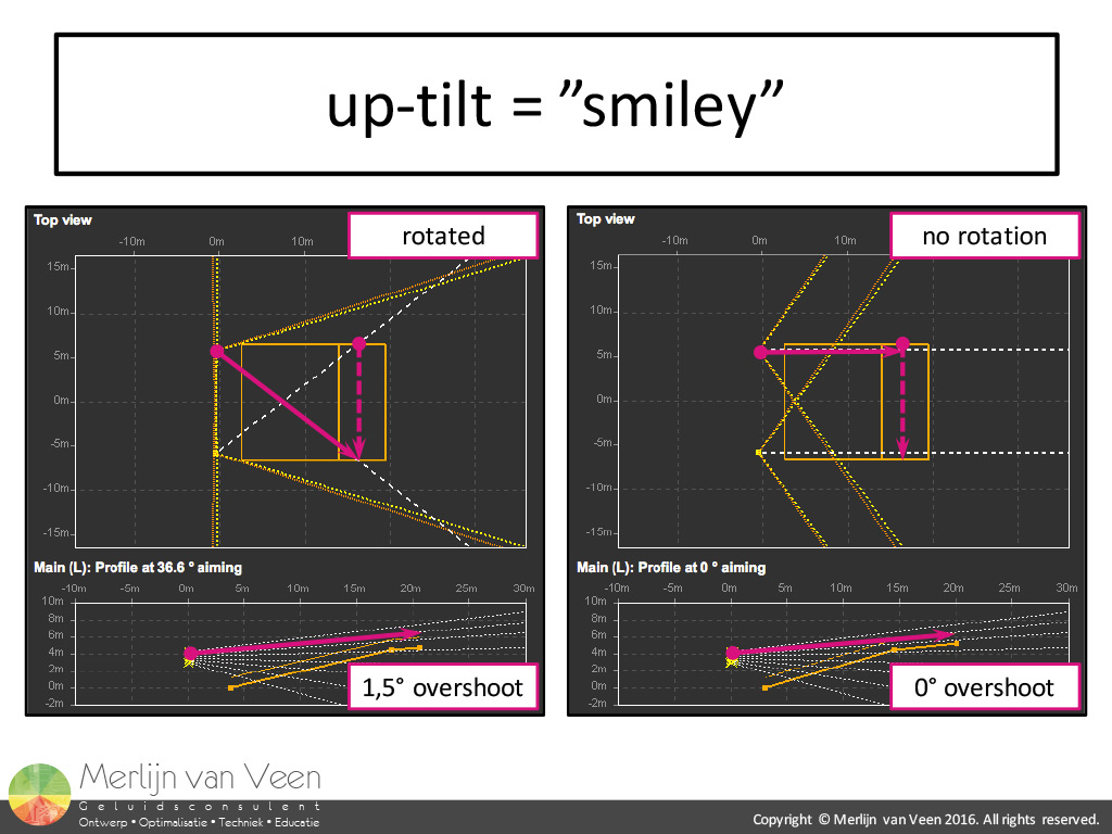 figure 8
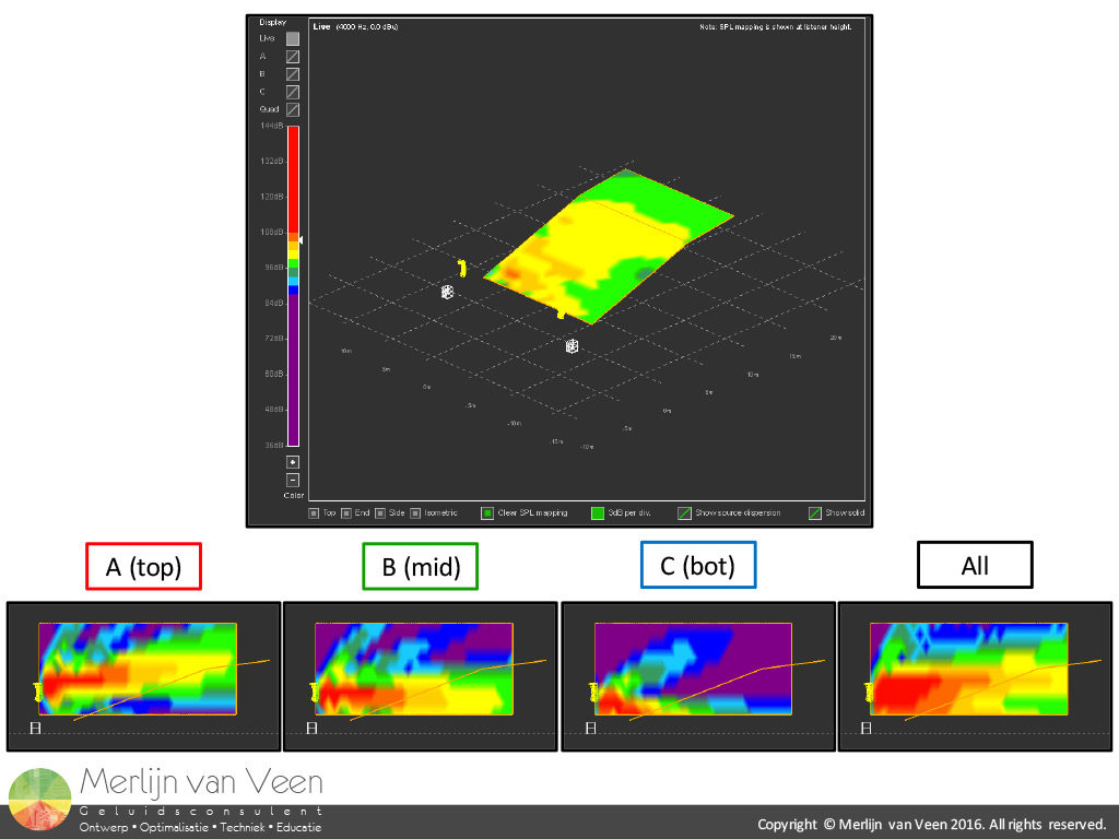 figure 9With line array speakers we're dealing with nominal coverage angles of as little as 5°. They behave like lasers in contrast to point-and-shoot speakers. There's no wiggle room. When left unaccounted for in case of up-tilt, the audience off axis in the last row near the array will be undershot. Adding extra up-tilt or coverage will improve their situation and the audience on axis at the opposite end of the same row is still being covered by the next speaker (figure 8). Same goes for a down-tilt situation. Extra coverage is required for the same reasons or the audience off axis in the first row near the array will be overshot.
Despite the course resolution of d&b ArrayCalc (1 meter), figure 9 shows equal levels from left to right in the 4 kHz octave for the majority of the audience. This is achieved by this so-called "cross-firing". The 6 dB difference front to back, was purposely maintained in anticipation of the subwoofers that can't keep up with the main speakers in terms of level loss over distance. Not doing so would result in tonal variance exceeding 6 dB. figure 10
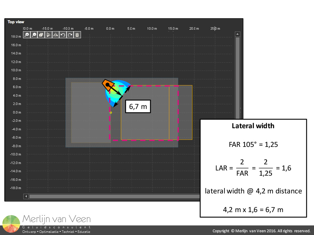 figure 11
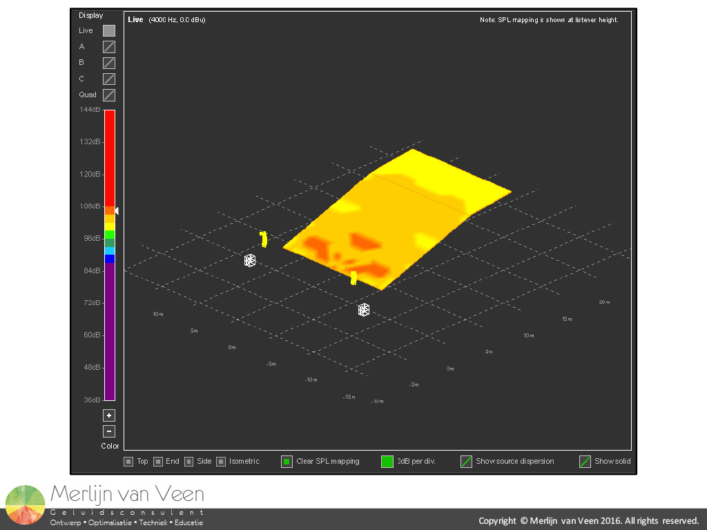 figure 12
Figure 10 shows the frequency responses at 3 different microphone positions on axis to the array and its respective symmetrical subdivisions. The black trace is the coherence weighted average. The only equalization used were high shelves in each segment to account for air losses and a global low shelf to reduce the LF coupling to a more modest gradual 6 dB ramp from 2 kHz to 125 Hz. The remaining low-mid surplus on axis to the entire array is typical line array behavior. It's a temporal problem that can be solved but not with the means at my disposal for this particular job.
To determine if I would be left with the typical gap front center, I resorted to the Lateral Aspect Ratio (figure 11) which allows us to determine the width of a speaker perpendicular to it, for a given distance. The lateral multiplier for a 105° speaker is 1,6 providing me with a width of 6,7 meter at a distance of 4,2 meter on axis to the bottom speaker.With a row-width of 14 meter no notable gap was left as is shown in figure 12 with both sides turned on.