
 There appears to be a lot of controversy regarding the workings of the L-Acoustics cardioid configuration. It's been suggested that it is achieved by means of all-pass filters. Is it a gradient or end-fire solution? In part 1 of this series of articles I will try to explain what I have come to think of as a hybrid approach.
DISCLAIMER: This is my personal "reverse engineered" analysis of this particular cardioid configuration. I'm not affiliated with L-Acoustics.
The easiest way of figuring out what a manufacturer is doing in terms of processing is by measuring the recommended processor or amplifier with onboard processing. figure 1
![preset no. 147 [FLAT_LA8]](/images/content/LA_cardioid/Flat_preset.jpg) figure 2
figure 2![preset no. 66 [SB18_100]](/images/content/LA_cardioid/single_SB18.jpg) figure 3In this instance a L-Acoustics LA8 amplifier using a custom made adapter cable from Neutrik NL4 to 1/4" jack (figure 1).
figure 3In this instance a L-Acoustics LA8 amplifier using a custom made adapter cable from Neutrik NL4 to 1/4" jack (figure 1).
To get a baseline reference I started by measuring preset no. 147 [FLAT_LA8] and apparently the LA8 has a latency (analog input) of 3,83 ms (figure 2) which is in accordance with the value of 3,9 ms published in the amplifier's specification sheet.
DISCLAIMER: Amplifiers are voltage multipliers!!! Should you decide to try and do this yourself, make sure the amplifier levels are turned all the way down before you begin. Use the line inputs of your audio interface because these signals can become HOT quickly. Once you've connected everything correctly, slowly turn up the amplifier levels until you're metering decent input levels.
Next step was to measure the default setting for a single SB18, the subwoofer used for these articles, using preset no. 66 [SB18_100]. Figure 3 shows the transfer function and reveals nothing unexpected. A HPF for speaker protection (over-excursion), a LPF to turn the speaker into a subwoofer and 2 PEQs (notches).
Modeling this behavior (with exception of the 2 PEQs) using AULab and CrossoverUnit suggests the HPF is something like Butterworth topology 4th order with a corner frequency of 30 Hz. The LPF appears to be Linkwitz-Riley topology 4th order with a corner frequency of 80 Hz.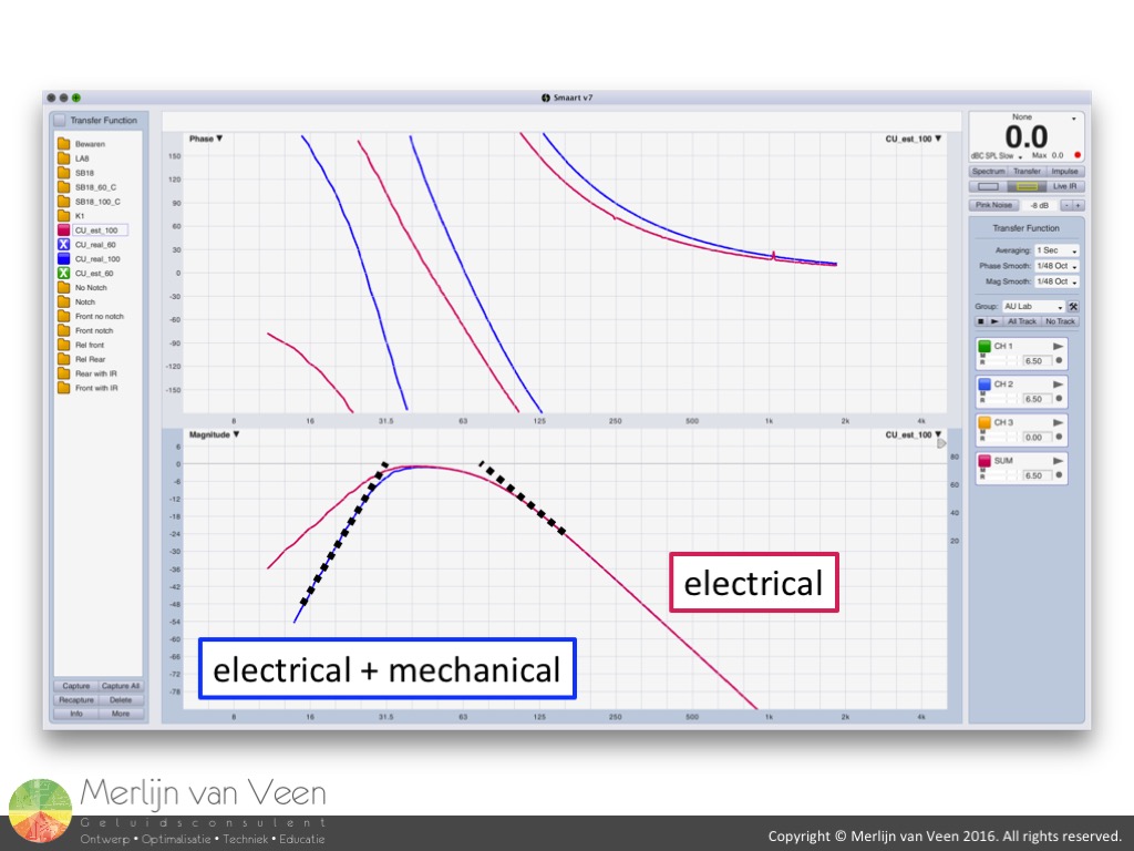 figure 4Mind you, these phase traces only show the electrical part of the story and not the compounded mechanical-acoustic phase shift introduced by a vented or ported design. The blue phase trace in figure 4, with typical 8th order high-pass behavior, is more likely to turn up on our screens when measuring a real SB18.
For the remainder of these articles we'll look at the electrical part only which suffices for determining relative differences.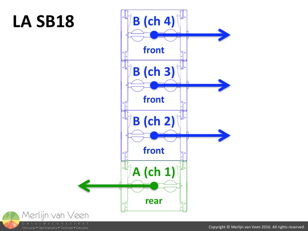 figure 5
![ch 1 and ch 2 of preset no. 68 [SB18_100_C]](/images/content/LA_cardioid/ch1_ch2_no_offset.jpg) figure 6
figure 6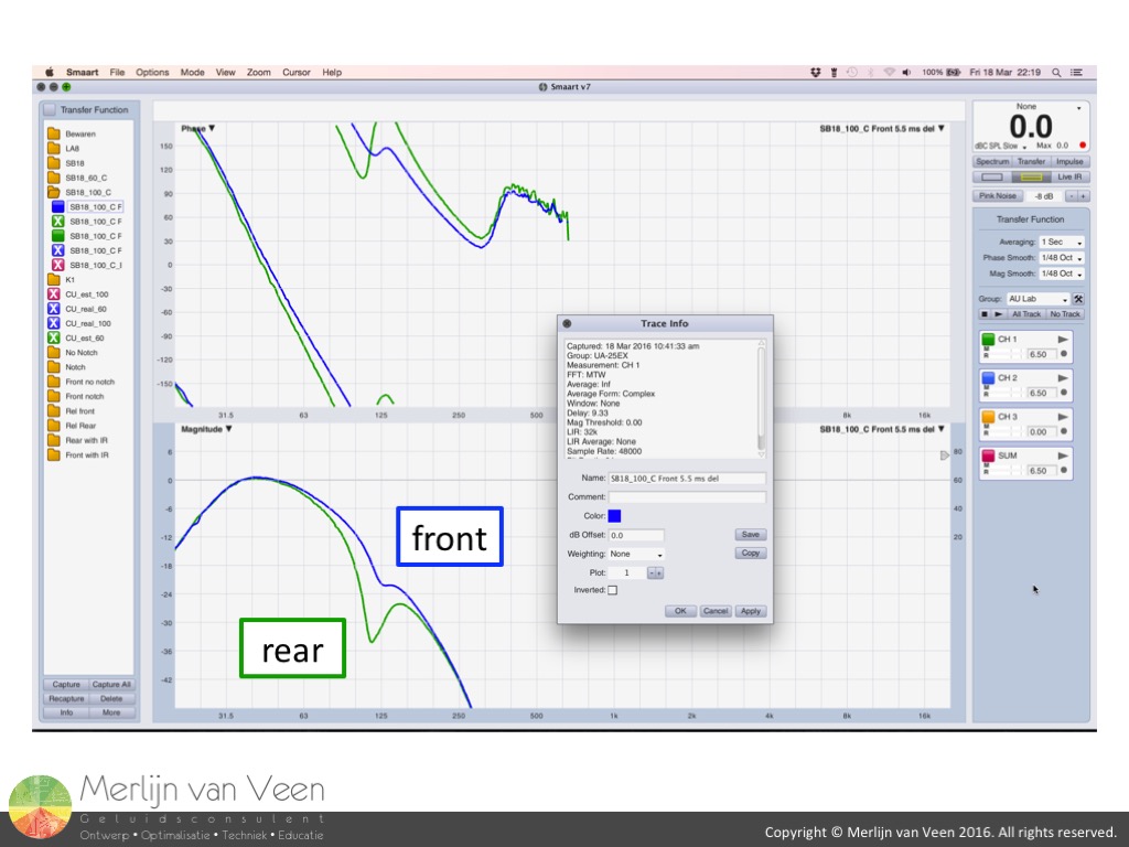 figure 7
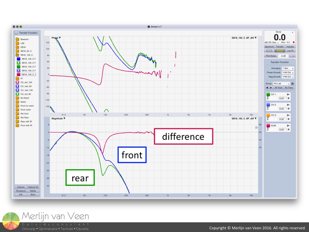 figure 8Figure 5 shows the typical LA cardioid setup with the top 3 speakers facing forward and the bottom speaker facing backwards. Using preset no. 68 [SB18_100_C], I can confirm channels 2 through 4 measure the same. So for the remainder of these articles we'll only look at channels 1 and 2.
Figure 6 shows the transfer functions of channels 1 (rear facing) and 2 (front facing). The increased steepness of the blue phase trace (front) indicates delay. I determined the delay by manually adjusting Smaart's delay locator until the phase traces overlapped again (figure 7) with the exception of a minor deviation. Subtraction of the delay locator values (9,33 ms - 3,83 ms) suggested 5,5 ms of electronic delay applied to channel 2 (front).
With the exception of delay, channel 2 (front) exhibits no additional processing compared to the non-cardioid preset no. 66 [SB18_100]. The same can't be said of channel 1 (rear). If we compare channel 1 over channel 2, accounting for the 5,5 ms of misalignment (figure 8), we can see an additional narrow notch filter (PEQ) has been applied to channel 1.
That sums up all the processing done in this preset. Let's resume:
- 5,5 ms of delay to channels 2 through 4
- additional single PEQ in ch 1
So no all-pass filters as was suggested by some and no polarity inversion of the back-firing subwoofer you would expect to see in a gradient solution. Up until now this particular approach has more in common with and end-fire solution.
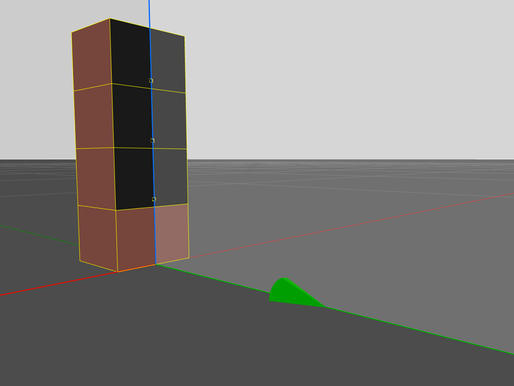
For more information regarding gradient and end-fire cardioid configurations consult the Subwoofer Array Designer manual.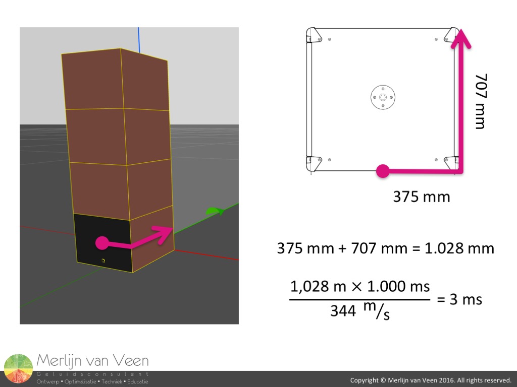 figure 9What the traces don't reveal at first glance is the time-of-flight involved by the physical displacement. Typical cardioid configurations require a certain amount of physical displacement. In any inverted stack approach the displacement is predetermined by the depth of the speaker enclosure. Figure 9 indicates it would take at least 3 ms for the sound to "wrap" around the subwoofer's enclosure.
Those 3 ms of time-of-flight would only require 3 ms of electronic delay to "push" back the forward-firing subwoofers and have all speakers arrive in time in front of the configuration causing summation. The total time offset behind the array would be the sum of those two values. Six milliseconds equals 180° of phase offset at 83 Hz producing a single null, one octave wide. Not exactly in the center of the operational range of a typical subwoofer. The subwoofer enclosure simply isn't deep enough to introduce enought time offset for useful cancellation at lower frequencies.
However the 5,5 ms used by L-Acoustics instead, plus 3 ms of time-of-flight equals 8,5 ms of time offset or 180° of phase offset at 59 Hz. A more logical choice for positioning that single null. Let's look at the outcome using these parameters.
In order to be able to appreciate the ingenious trick with the notch filter in the rear-facing subwoofer, we first need to look at the results without it. For this reason I will continue to use the modeled responses and add the notch later by means of a PEQ.  figure 10
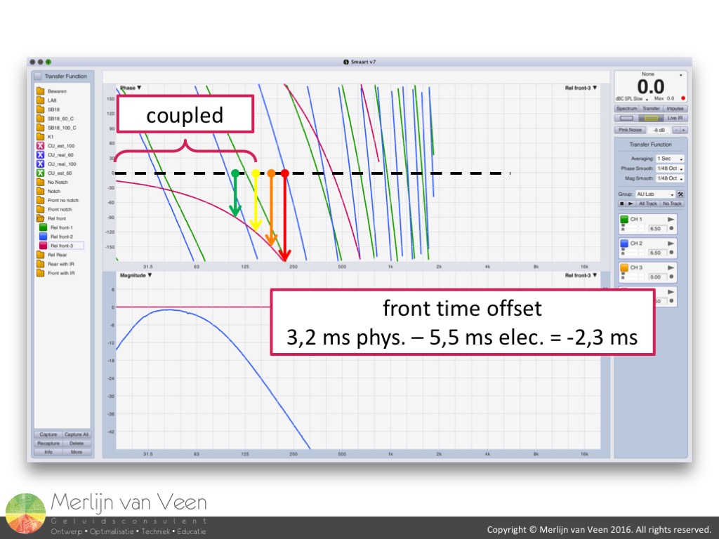 figure 11
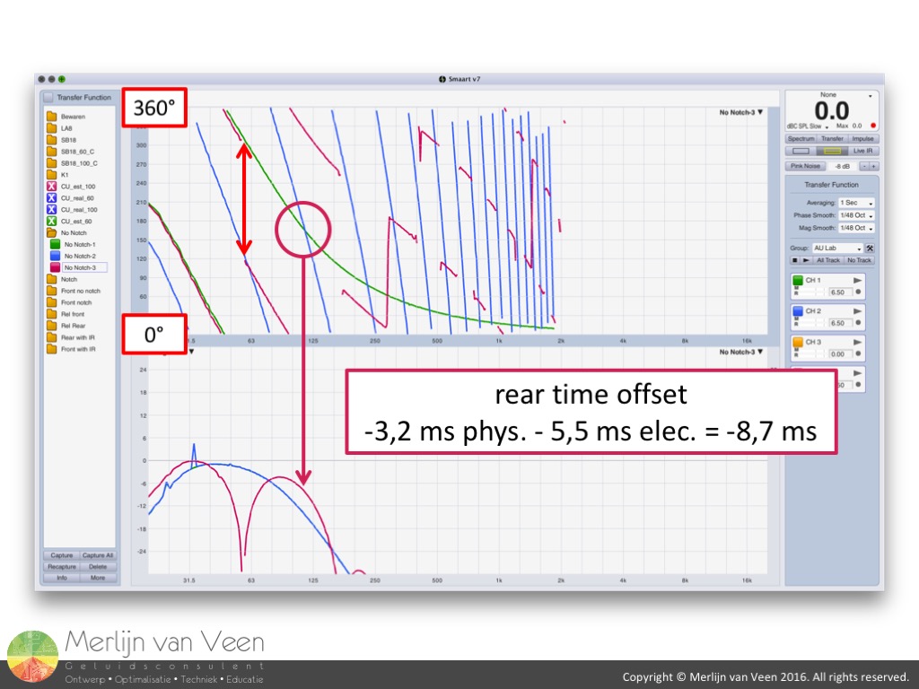 figure 12
 figure 13
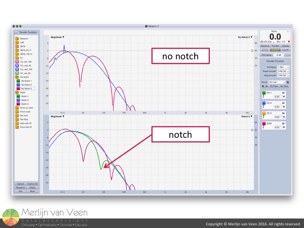 figure 14
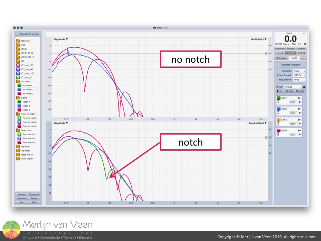 figure 15Figure 10 shows summation in front of the configuration even though the phase slopes don't match because of the over-delaying by 2,3 ms. Figure 11 shows the relative differences and that coupling (120° phase offset or less) is maintained up to 150 Hz. Atypical behavior for an end-fire configuration bordering gradient behavior (in phase out of time).
It's this behavior why I'm inclined to think of this solution as a hybrid approach. True end-fire is time aligned with 0° phase offset for all frequencies and not stretched until finally uncoupled.
Figure 12 shows cancellation behind the configuration but also a peak at 115 Hz, the critical frequency and no go area of a typical end-fire configuration, where both subwoofers are in phase again but one cycle apart. In figure 13, showing relative differences, this is even more apparent.
This is the trade-off for lowering that single null in frequency. One cycle (360°) of 115 Hz equals 8,7 ms of time offset made up by 5,5 ms of electrical delay and 3,2 ms of time-of-flight. The very frequency where the notch in the rear-firing subwoofer comes into play.
The only way of solving this out-of-range peak, under such conditions, is by level-isolating the subwoofers. This is exactly what the notch does by lowering the level for those frequencies by 17 dB, handing custody over to the front-firing subwoofers. In other words:
- above 80 Hz - front subwoofers, sole custody
- below 80 Hz - all subwoofers, joint custody
The bottom plot in figure 14 shows the reduced peak at 115 Hz when the notch is introduced in the rear-facing subwoofer, improving rear behavior. As far as I can tell that's all there's to this particular configuration. Let's look at the differences between front and back.
Figure 15 shows improved behavior on both sides of the configuration when the notch is applied. The level offset at 115 Hz reduces summation behind the configuration and at the same time cancellation in the front. A win-win solution because without the notch the configuration is actually louder for frequencies above 90 Hz behind the configuration than in front of it. Providing 5 dB of extra front-2-back difference at 90 Hz. Finally let's look at the results using the real transfer functions instead of the modeled ones.
Smaart v7 allows us to measure impulse responses (IR mode) and store these as WAV files. Impulse responses are nothing but the time domain representation of the same information. I measured the IR's of channels 1 and 2 of the LA8 amplifier with a synchronized sweep and a window or FFT size of 32K samples (0,7 seconds). That fixed window length makes these impulse responses by definition finite as in FIR (Finite Impulse Response).
Using LAConvoler I can import the FIR WAV files into my AULab environment and measure their transfer functions, as you would measure any other plugin, taking away the need to model them using an entire filter bank and / or numerous instances of CrossoverUnit or other plugins.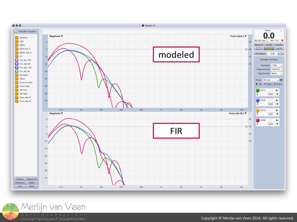 figure 16The bottom plot in figure 16 shows the real thing, including the 2 notches that are inherit to the tuning of the individual SB18's we measured with the non-cardioid preset no. 66 [SB18_100]. The 3,2 ms time-of-flight was introduced by means of a delay plugin. As you can see, with exception of the 2 notches, there are no substantial differences between the modeled and real responses.
Up until now, we've only looked at the interaction between channels 1 (rear) and 2 (front). Assuming perfect omnidirectional behavior and disregarding the other 2 front-facing subwoofers.
In part 2 of this series of articles I will investigate the effects of the inherit front-2-back level differences of a single SB18, relative level (ratio of front- to rear-facing subwoofers) and coupling with the floor.
With the exception of Smaart v7 all tools in this article are freely available.