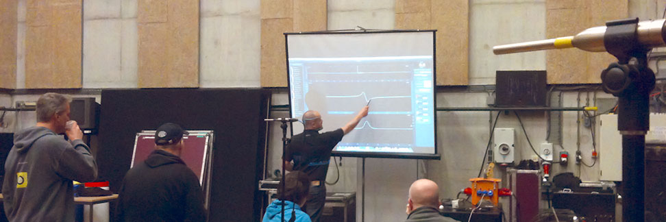
 A while ago I was able to attend the very first Danley demo hosted by Firm4 in cooperation with RF Shows in this small corner of the world. Having read numerous animated threads at the ProSoundWeb forum about the distinguishing qualities of these products, I was very eager to finally experience Danley for myself. It was a very inspiring phenomenon, so much that I intended on doing my own production within two weeks time. Keep on reading for full disclosure on a very remarkable event. The premiere of Danley products in a theatrical production in The Netherlands.
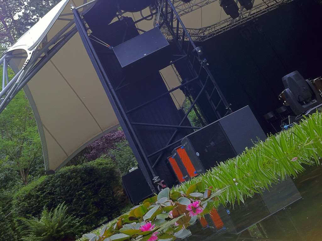
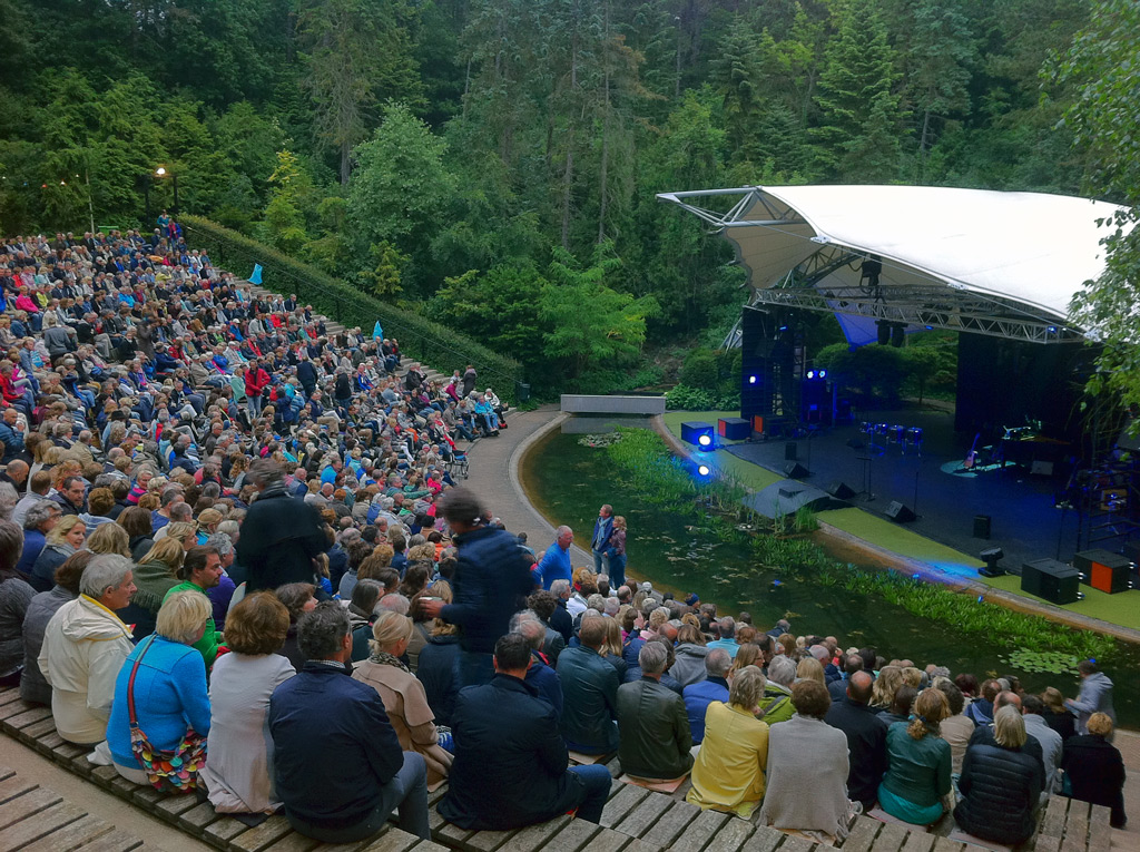
The venue I had in mind is an open-air amphitheater that houses 1.400 spectators. The house system consists of a d&b audiotechnik T-series line array in a dual-mono fashion, complemented by V-series subwoofers (9 x T10 speakers and 2 x V-SUB cardioid subwoofers per side). This was the system I used in previous years and wanted to rival in terms of power, coverage, tonality and fidelity.
The venue has a first row to last row ratio of 2:1, which allows for a single speaker per side approach. No need for subdivision by traditional means (asymmetric coupled point source) or line array. Also the absence of a roof gave me the freedom to point and shoot without worrying about potential reflections from the ceiling.
Doing some rudimentary calculations with the gear at my disposal in mind, I figured the SH96HO (Synergy Horn 90° x 60° High Output) was the best candidate. For the subwoofers I wanted to incorporate the cardioid solution of the house system with respect to noise pollution (the venue is located in a residential area). I decided on 3 x TH118 (Tapped Horn single 18”) subwoofers in a end-fire configuration per side. This way I’d realize rear cancellation without sacrificing power.
After a site survey where I gathered all relevant data and measurements, I modeled the venue in SketchUp. The model was then exported very conveniently into Danley’s proprietary prediction software called Direct using a Danley proprietary plug-in for SketchUp. Within minutes I was looking at the predicted SPL for the products I had in mind. After gaining confidence about the approach I moved forward. Future design adjustments would be done on site.
I needed these shows to go right because in the eyes of the uninitiated I was about to have a perfectly capable system taken out, in place of something that “looked” like we went 20 years back in time. Also in front of my peers and the house technicians I wanted to at least equal the house system and prove that the technology works. That’s why I insisted on help from the factory to turn it into a success.
I’m reluctant of using active sound systems. To many variables, to much layers of complexity and as a result room for operator errors. Therefore I demand factory presets, regardless of the speaker brand. This presented one particular challenge however. Having no disposal of proprietary Danley DSP units, I needed to create my own presets. This might sound like simply copying some numerical parameters, but those who read Bennett Prescott’s “DSP tower of Babel” know that unfortunately live is less romantic.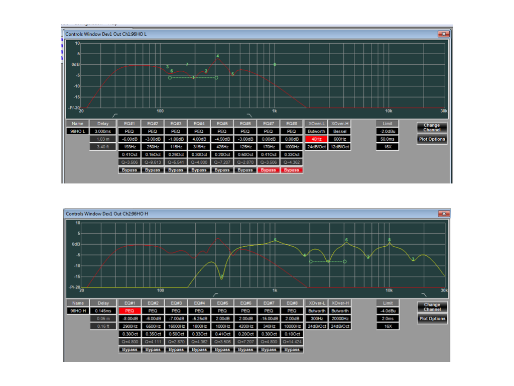 Figure 1
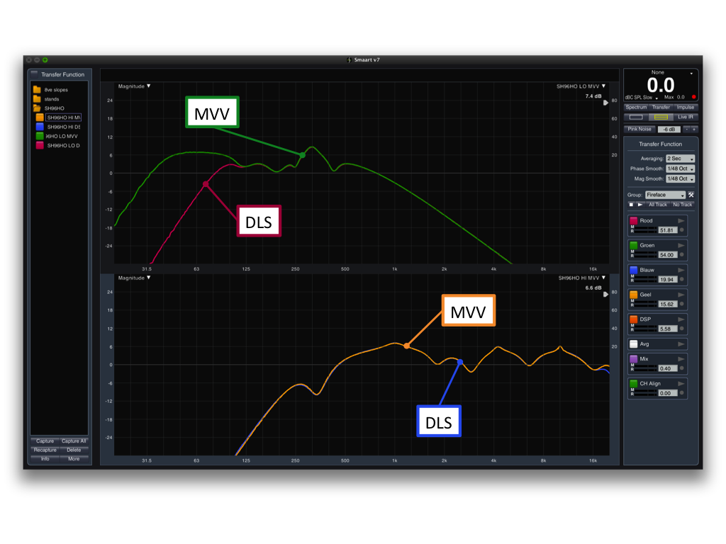 Figure 2Ivan Beaver of Danley was kind enough to provide me with the preset values (Figure 1) and in addition a set of transfer functions made with Smaart v.7 of both DSP channels on my explicit request. Using those figures as a starting point and the transfer functions imported into Smaart as reference, I was able to measure my Dolby Lake processor and recreate the settings with great accuracy in terms of magnitude and equally important, phase. Figure 2 shows the transfer functions at near completion.
Another challenge lied in the fact that the recommended impedance for the LF section of the SH96HO when powered actively (bi-amp) is 2 Ohm. This is by all means a heavy, current devouring, load and few amplifiers handle it gracefully at near full power conditions. Also the 2 Ohm operation greatly restricts speaker cable length. Since both main speakers needed to be powered from one side of the stage for logistical reasons, the SH96HO’s LF section was set to 8 Ohm using the toggle switch on the back of the cabinet. This allowed me to quadruple speaker cable length using identical wire diameter and stop worrying about voltage sagging and circuit breakers kicking in.
All amplifiers where from MC2 Audio, a brand ran by the same importer as the speakers. I ended up using 2 x 2-channel amplifiers for the main speakers. The E90 (continuous sine 2.400 WRMS 8 Ohm) for the LF section and the E45 (continuous sine 2.050 WRMS 4 Ohm) for the MF+HF section. For the subwoofers 2 x 4-channel E100 (continuous sine 2.250 WRMS 4 Ohm) amplifiers where used to allow for the unique processing required for each individual subwoofer in a end-fire configuration.
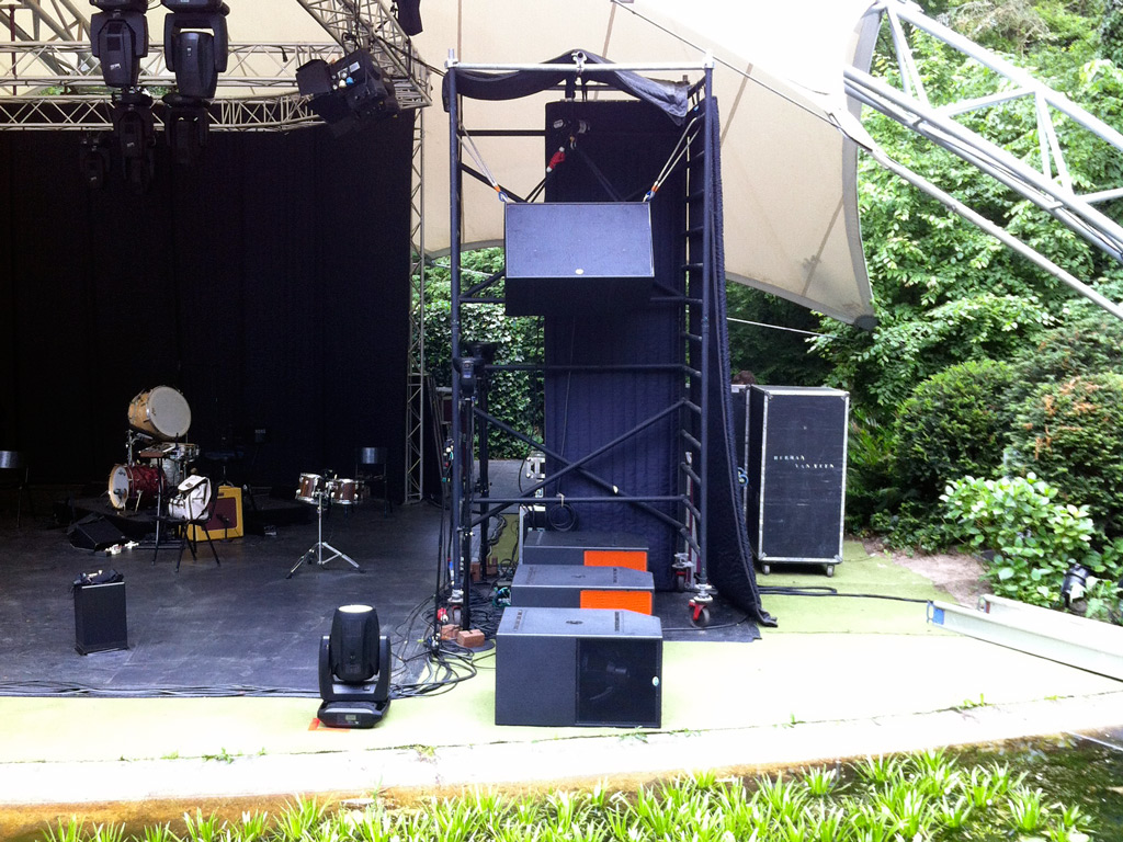
On site both speakers where flown with “relative” ease into scaffolding towers. The front-end was dead hung and the rear-end picked up by a chain hoist allowing me to introduce inclination at my desire. The eye bolts where imperial sizes and I strongly encourage Danley to outfit future products intended for the European market (amongst others) with metric size hardware.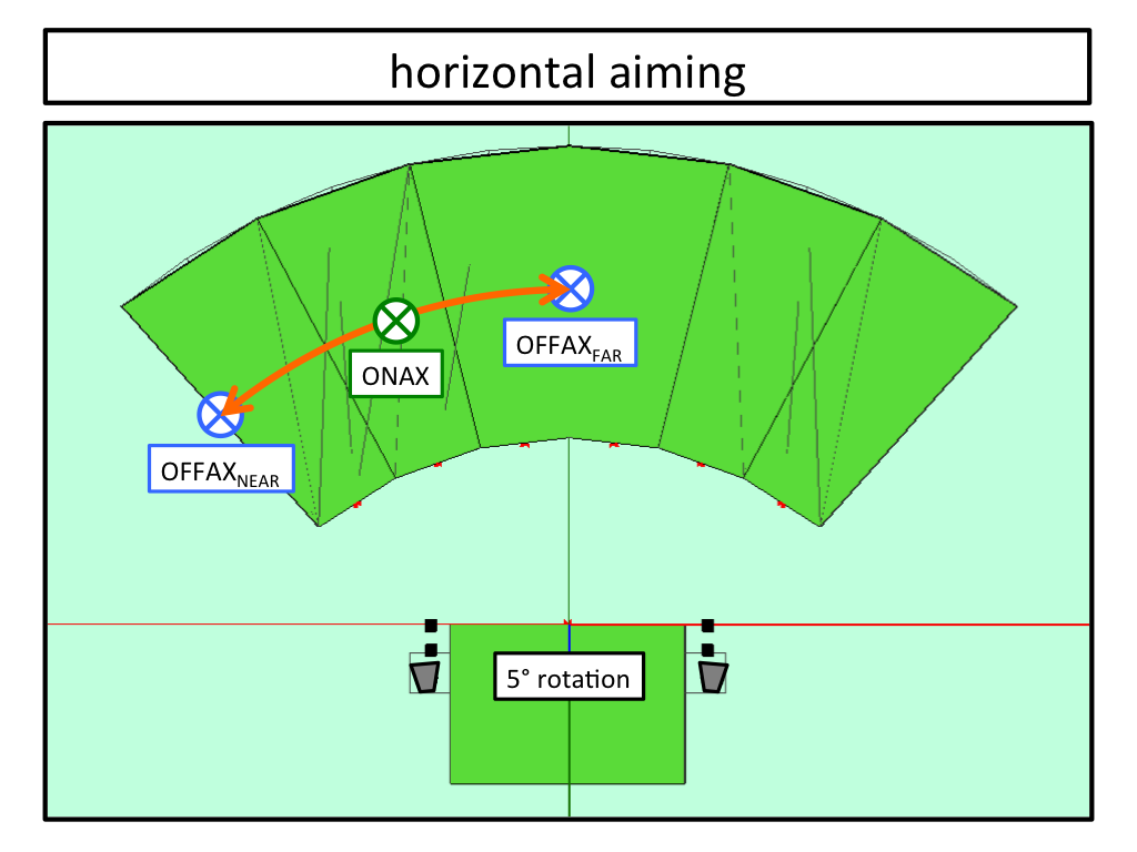 Figure 3
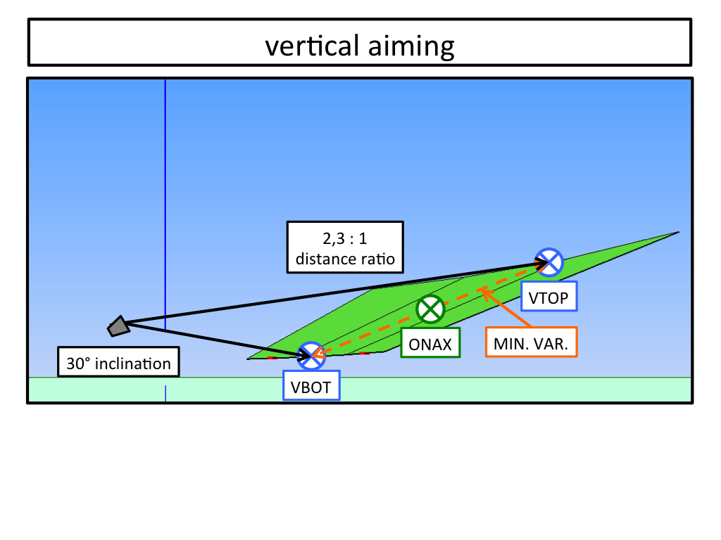 Figure 4Once the speakers where up in the air the process of aiming them started with one side of the audience. Four measurement microphones where placed at carefully chosen positions (Figures 3 & 4). I began with horizontal rotation by rotating the complete scaffold, making sure the frequency response at OFFAXNEAR and OFFAXFAR was identical. The result of 5° outwards was in perfect agreement with the prediction software.
Next was inclination (vertical rotation) again making sure the difference between VBOT and VTOP was a small as possible both in terms of relative level and tonality. In contrast to the prediction software where I decided on 20° to 25° of positive tilt, on site I settled for 30°. This resulted in the least relative level difference of 3 dB front to back and no spectral variance.
The discrepancy of 5° to 10° however bothered me quite much, not to mention it looked weird. The speakers where aiming at the tops of the tree line behind the audience. Fortunately I care less about the latter as long as it measures and sounds right in random order. I did however do some further investigating afterwards.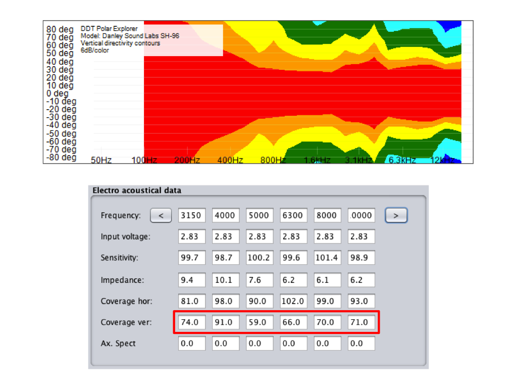 Figure 5Close inspection of the SH96HO in the Direct project file showed considerable energy projected off-axis in the vertical plane beyond the specified coverage angle of 60° for the 4 kHz and 8 kHz octave bands (Figure 7). This is underscored in both Danley’s Polar Explorer and the proprietary CLF (Common Loudspeaker Format) viewer at their website. Using the SH96, the SH96HO’s closest relative, a fair amount of wiggle room is showed in Figure 5. I can only speculate that Danley rightly used a nominal but conservative figure to rate vertical coverage.
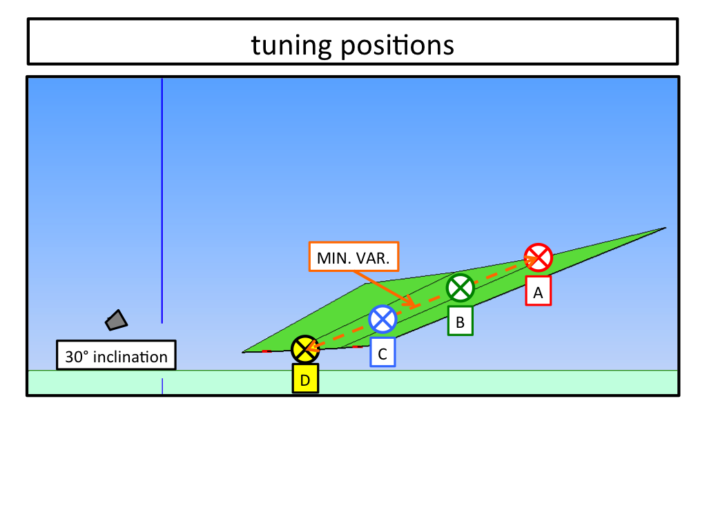 Figure 6
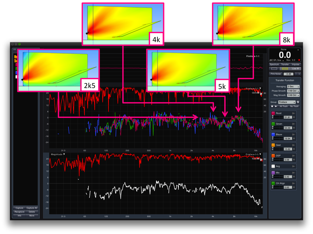 Figure 7
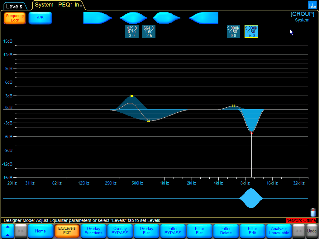 Figure 8
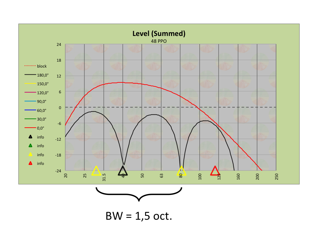 Figure 9For tuning purposes the 4 microphones where placed on axis in the horizontal plane and distributed equally between VBOT and VTOP in the vertical plane (Figure 6). Because of the different amps used for the LF and MF+HF sections of the main speakers, relative levels where set during this step in an attempt to achieve the flattest response. The MF+HF section was turned down by 3 dB.
Figure 7 shows a very consistent trend front to back of the main speakers. Thanks to my great archiving skills these where the only traces left. The white trace in the bottom window is the coherence weighted average. Figure 8 shows all the equalization that was applied to the main speakers.
I intended to cross over to the subwoofers around 80 Hz and for this purpose I chose to move the HPF of the LF output channel to the input section of the entire crossover module at my own discretion, affecting both channels from then on equally. In contrast to the specified preset settings and values, this provided me with the freedom to determine the actual crossover frequency without affecting the alignment between the LF and MF+HF sections on site. This approach forced me however to re-align the LF and MF+HF sections. And the specified delay time applied to the LF channel was adjusted from 3 ms to 1,5 ms resulting in matched phase slopes again.
The end-fire configuration (Figure 9) was designed in SAD and optimized for operation of 30 Hz through 80 Hz. Spacing was 1,4 meters (4,6 feet). This provided 13,5 dB of rear cancellation on average. The predicted and measured delay times where within a couple of tenths of milliseconds. Finally the main speakers where aligned to the subwoofers, relative levels where set and I was anxious to finally hear something else than pink noise.
The easiest feature to experience is the system’s “immunity” to wind. If you’re used to working with line arrays most of the time like I am, it’s a really weird counterintuitive sensation not having the sound being “blown” away when the wind picks up. But the real fun begins when you start walking the venue.
Never before have I experienced such smooth seamless and uniform coverage without sudden changes in either level and/or tonality throughout the entire audience. Even the transition from left to right was super fluid. It’s a real pity the audience is static because they won’t be able to appreciate these exceptional aspects.
The system was scaled properly and allowed me to gracefully achieve 110 dBC slow without effort. Judging by the limiter action on my tablet PC, which where set to the best of my abilities, the subwoofers where the first to run out of gas, but only on the occasional kick drum note in loud passages. I did not have visual confirmation from the amplifier meters and remote monitoring over network was unavailable.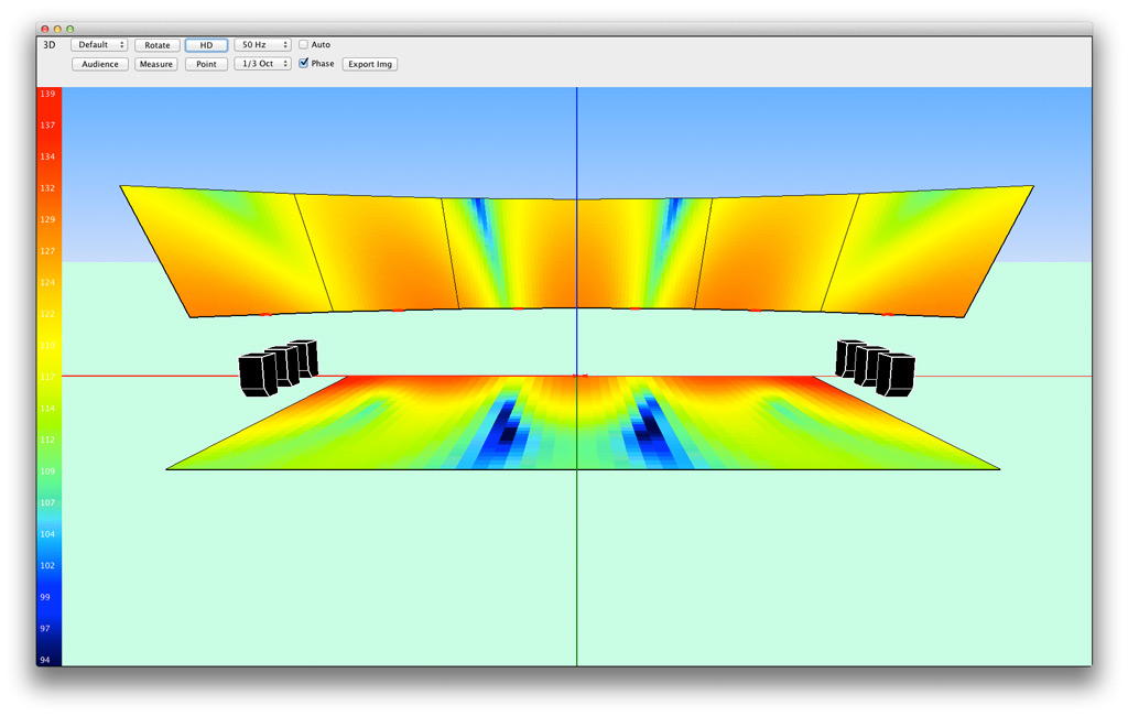 Figure 10The house technicians where impressed and didn't expect such a big sound from such a small looking speaker. Descriptors like "directness" and "enveloping" were uttered. Ironically the only thing most people noticed where the power alleys and valleys inherent to a LR subwoofer setup (Figure 10). This is in no way exclusive behavior and meant to me there was apparently little to comment on the Synergy Horn technology.
Based on this experience I do hope Danley either starts rolling out presets for common DSP devices or diverts to self-contained closed products exclusively. Making your own presets is less than ideal, especially with so many different types of speakers, and should be done by the manufacturer. As with any 3-way system a few all-pass or FIR filters go a long way. If some of the phase shift can be accounted for, the impulse response will tighten and the speaker will play nice in terms of relative time with other products. Even from different manufactures.
The system is very responsive and as such not for the faint of heart. Garbage in, garbage out. I felt the speakers sounded a little bit coarse on this specific occasion but the technology is sound and works. I'm very much looking forward to more exploration in the future if suitable venues, in my opinion, present themselves. If you are in the position to experience Danley products for yourself I strongly encourage you to do so. This is definitely not EDM only! Gallery
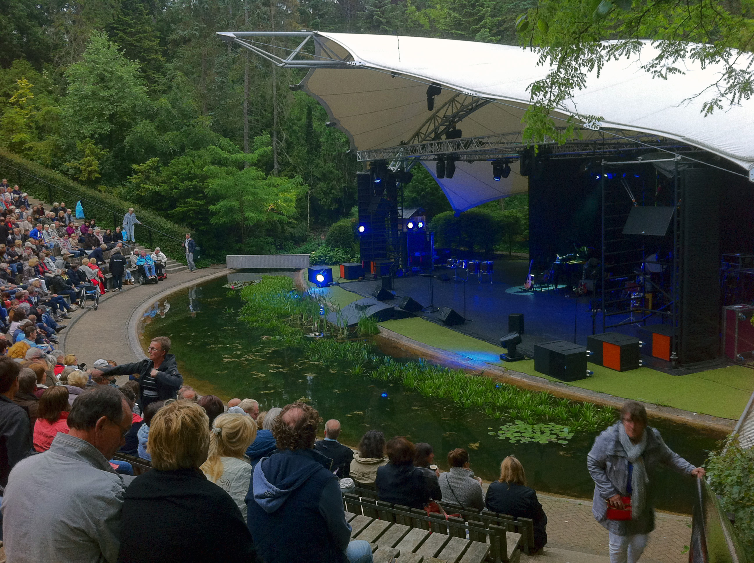

 I would like to express a great many of thanks to Robert Pigeaud of Firm4 and Jeroen Kwakernaak for their support, equipment, time and effort. Without them I would have nothing to write about. Thanks for the confidence!
Danley Sound Labs
Firm4
RF Shows
MC2 Audio
The archive below contains both SketchUp and Direct files used in the design process.