
 figure 1One of the biggest challenges every new generation of sound engineers appears to struggle with is learning how to phase align subwoofers to mains. A quest which at one point in my early career felt like impossible.
In this article, I will disclose the method which has been working flawlessly for me in the past couple of years. It's a two-step process consisting of a relative and absolute part.
Most of the time is spent on the relative part, which you have to do only once. However, it's time well invested because it turns the absolute part on site into a five-minute job at most.
The relative part's sole purpose is to convince yourself that the entire sound system is appropriately phase aligned when the loudspeaker grills are flush, living in the same plane (coplanar). If the sound system doesn't meet that condition, the challenge will become to "pre-align" the loudspeakers until it does.
Conduct the relative part in the near field where signal-to-noise (SNR) and direct-to-reverberant (D/R) ratios are favorable, providing high-coherent, actionable data. Data that tells you which buttons to press to achieve a successful alignment.
Anyone that has attempted to do phase alignment in the far field knows from experience that room interaction will likely make the phase traces go FUBAR unless you happen to be outside.
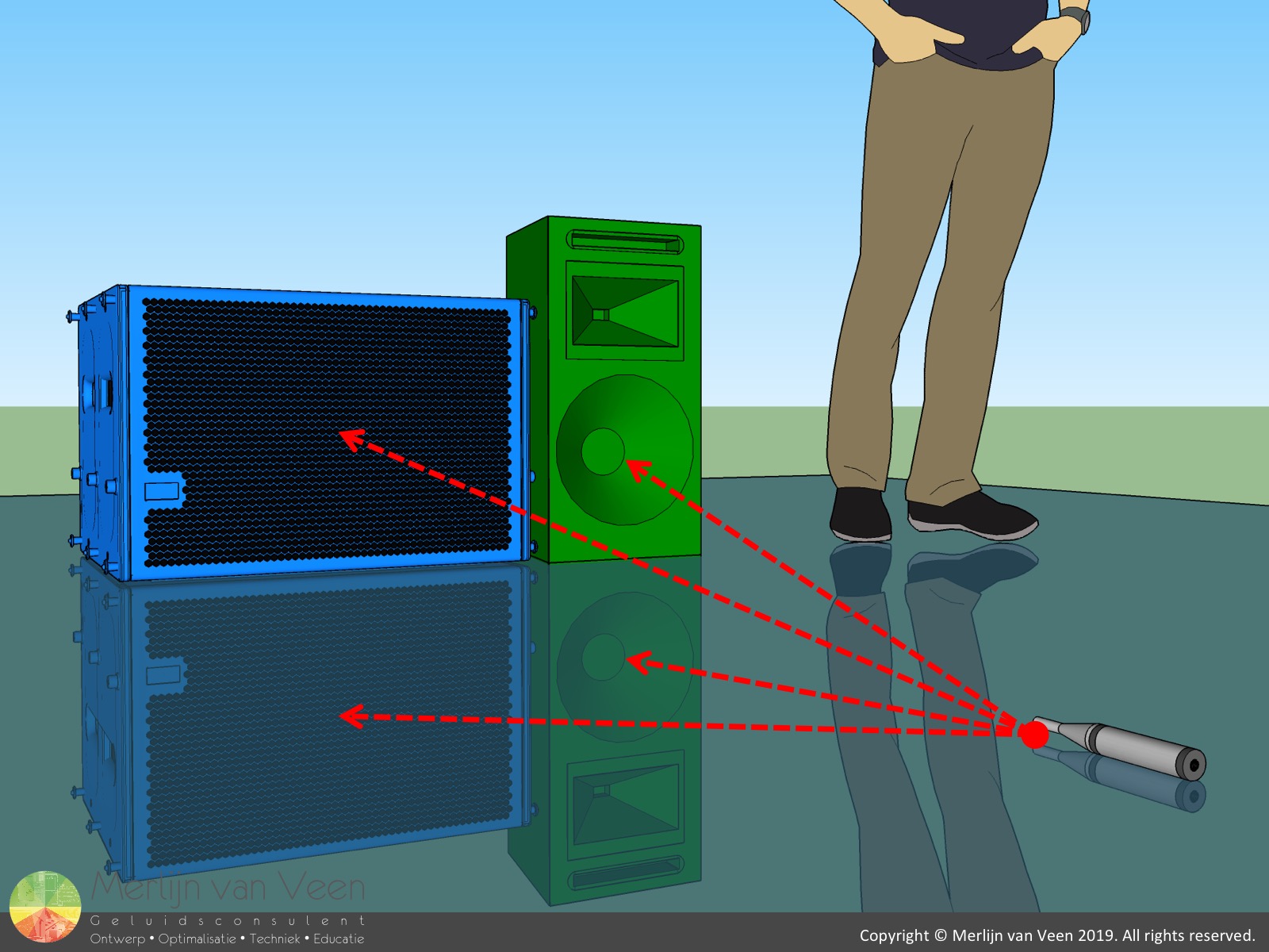
Place a measurement microphone on the floor (half space) equidistant to the grills (figure 1) but not so close that the direct radiators start to dominate over the ports (vents) or vice versa. Typically, anywhere from one to two meter suffices. Aim for coherence values of ninety-five percent or more in the frequency range of interest.
"Amplitude always wins but, when levels are matched, phase is the tiebreaker."
Bob "6o6" McCarthy
Set level first
Solo the main loudspeaker and use the delay finder to synchronize to its arrival time. From now on, it's absolutely mission critical that you don't touch the delay finder ever again for the remainder of this procedure! Store the main loudspeaker's trace.
Solo the subwoofer and set its level to match the main loudspeaker's level (unity gain). We'll discuss "Up to eleven" (This is Spinal Tap) later. Store the subwoofer's trace.
Based on these two traces, you first need to determine the frequency span where phase alignment is mandatory until level offset (isolation) comes to the rescue and time no longer matters.
Watch the video below to see these steps in action.
Notice the excellent coherence. This is all signal and little to no noise. Such is the near field's power. Actionable data!
By making clever use of the analyzer's offset function, I was able to easily identify the frequency span where both loudspeakers have shared custody and level offsets are within 10 dB or less.
In this four-thirds of an octave-wide interval, phase alignment is mandatory if serious ripple is to be prevented. Below 54 Hz however, the subwoofer is sole custodian once it dominates by 10 dB or more over the main loudspeaker and time no longer matters. The same is true for the main loudspeaker above 125 Hz.
For more information regarding isolation, ripple and the other summation zones, please consult the chapter "Summation" which you'll find in all three editions of Bob McCarthy's book "Sound Systems: Design and Optimization".
How to read phase
Now that we've identified the frequency range of interest, we can start looking at the phase traces. But, before we proceed let's establish some ground rules.
The three trends we saw in the video, which can occur anywhere in the audible spectrum, are:
- flat phase trace (no slope) = measurement and reference are in time
- "rising" positive slope = measurement is leading (early) with respect to reference
- "declining" negative slope = measurement is lagging (late) with respect to reference
 figure 2More slope (secant or tangent line) in the same frequency span implies more time offset and vice versa (figure 2).
When in doubt, consider spending some time with the phase calculator to gain more insight.
First attempt
Let's attempt at putting our understanding of reading phase traces into practice.
In the video above, I cycled the phase axis to cosmetically relocate any wraparounds in the phase traces from my field of view (frequency range of interest).
With the wraparounds out of the way, I can determine the slopes' steepness. When in doubt, you can resort to a tool like PixelStick to measure the angle of the secant or tangent lines.
Of the two traces, in the frequency span of interest, the blue subwoofer trace is steeper and therefor the later. It's my understanding that time travel is not possible yet (as far as I know), so our only option is to make the main loudspeaker equally late as the subwoofer, by introducing delay. figure 3Adding delay will increase the steepness (figure 2) of the main loudspeaker's green phase trace which will then "spiral down" and exit the phase plot in the bottom only to wrap around and reappear at the graphs's top (figure 3) where it continuous its journey (check the phase calculator).
However, I'm strongly opposed to arbitrarily playing around with delay and polarity, hoping for a "happy accident" (Bob Ross).
In anticipation of the "spiraling" wraparound phenomenon, I chose an arbitrary frequency, preferably somewhere in the crossover range, which I used as starting point for a simple calculation.
I went for 100 Hz because it makes for easy math. But, any other frequency will work as well, provided that that frequency and its immediate neighbors are represented by high-coherent, actionable data.
\begin{equation}\Delta t=\frac{\phi }{360}\times\frac{1000}{f}\end{equation}
Using equation 1, knowing that I can rely on the data, I calculated that it will take 6,7 ms of delay to introduce a 240° phase offset for 100 Hz and 100 Hz alone!
This time offset succeeded at introducing an intersection between the green (main loudspeaker) phase trace and the blue (subwoofer) phase trace at 100 Hz.
However, being in phase should never ever be mistaken for being in time which is confirmed by the mismatch in slopes.
After introducing the delay, the green (main loudspeaker) phase trace is now steeper (and therefor later) than the blue (subwoofer) trace. Apparently, I introduced too much delay.
Partial success
I call this intermediate result "partial success". We've managed to successfully phase align 100 Hz and I'm not willing to give that up!
Regrettably, a crossover is not a one-note event. In this instance it involves a four-thirds of an octave-wide exchange where all frequencies (including 100 Hz) must be phase aligned.
I somehow want to tilt my main loudspeaker's green phase trace, like a seesaw, around my 100 Hz "pivot" frequency where I'm already successful.
The phase trace slopes informed me that I need to take out delay for the main loudspeaker. But, whatever value we subtract from our initial 6,7 ms delay should preserve my successful phase alignment at 100 Hz!
Second Attempt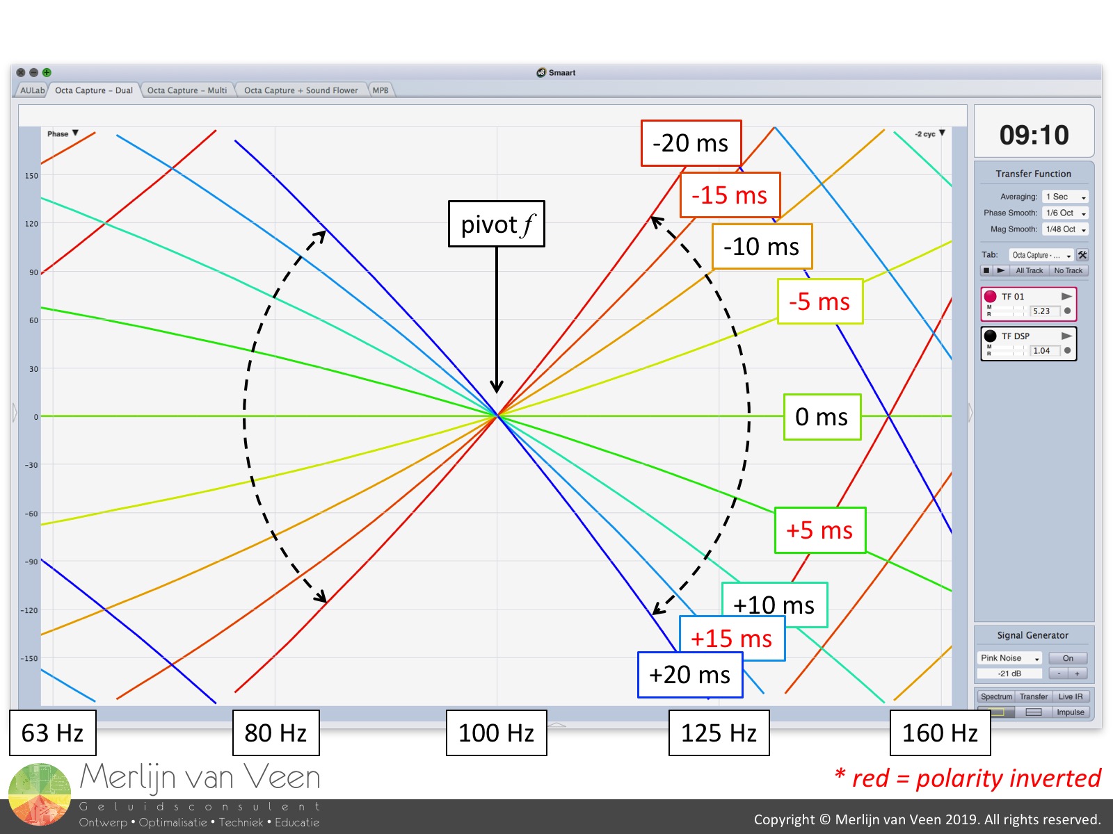 figure 4Phase alignment can always be preserved for a single frequency as long as you add or subtract \(n\) cycles or \(\left(n+0,5\right)\) cycles (in combination with a polarity reversal) worth of time offset where \(n\) can also be zero, i.e., half a cycle (figure 4).
So, if I want to reduce the 6,7 ms delay while preserving the 100 Hz phase aligment, I could start by substracting 5 ms (half a cycle of 100 Hz) in combination with a polarity reversal.
Notice that by taking out 5 ms, I introduced a 180° degree phase offset at 100 Hz which was to be expected. But, using PixelStick, I determined that the slopes of both phase traces matched throughout the crossover range.
In fact, using PixelStick as a 180-degree-tall "benchmark", there appeared to be 180° of offset for all frequencies (including 100 Hz) throughout the crossover range. So reversing the polarity will not only fix 100 Hz but also all other frequencies of interest.
Ultimately, which polarity you choose to reverse is your prerogative, as long as you apply it to one loudspeaker exclusively. In the real-world I would have gone for the subwoofer instead of the main loudspeaker.
In this instance, half a cycle in combination with a polarity reversal did the trick. In practice, it's all about finding the correct number of \(n\) cycles or \(\left(n+0,5\right)\) cycles (in combination with a polarity reversal) that results in matched slopes that overlap around a certain pivot-frequency that you are free to choose.
For more information on the importance of matching slopes please watch this video.
Corridor of 60°
Things are looking very good and I want a metric to inform me if my solution needs further refinement or not. Do my phase traces overlap and are their slopes matched for the frequency range of interest? Have I achieved the best possible fit?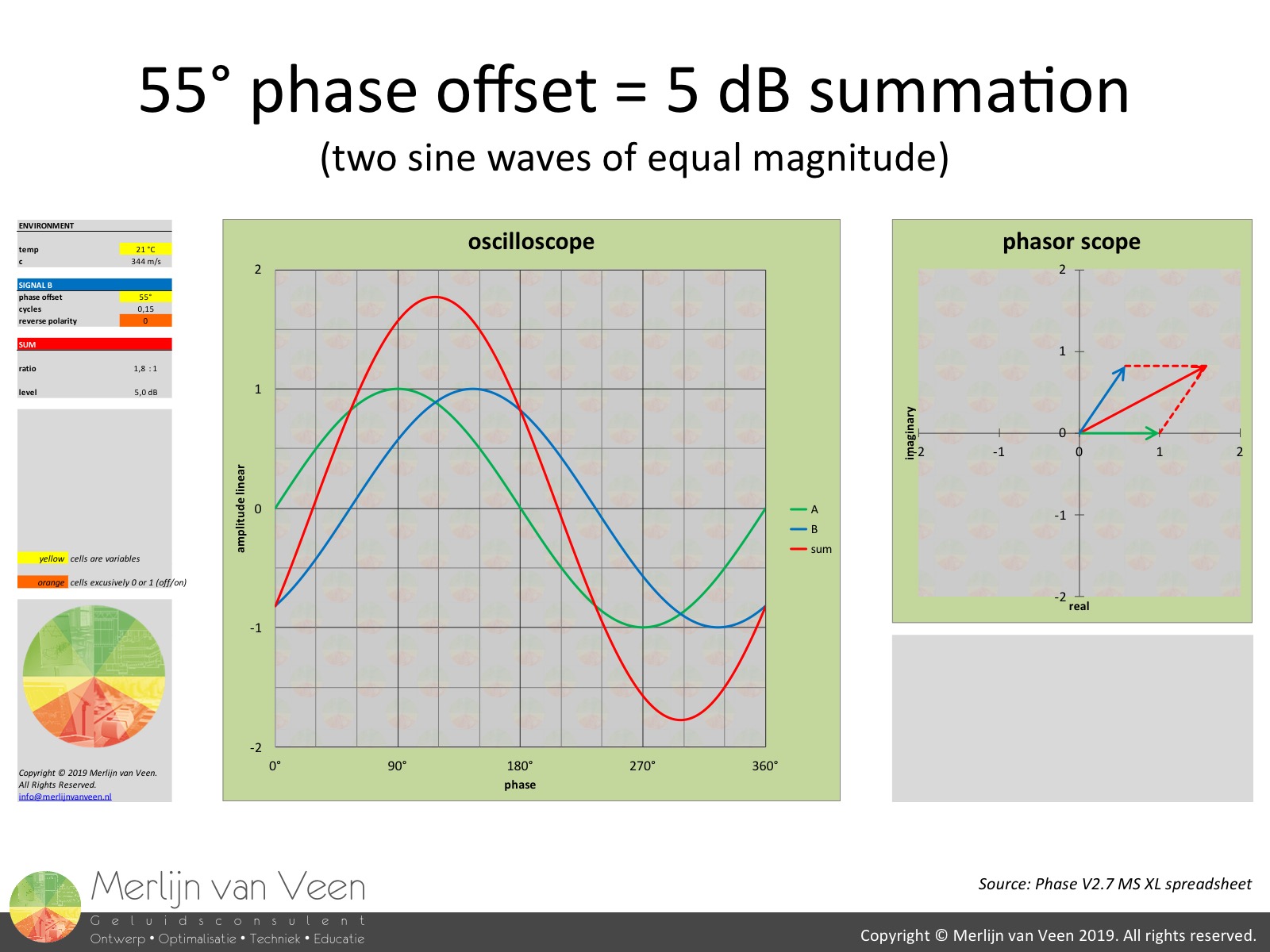 figure 5When you sum two sine waves (pure tones) of equal magnitude but with 55° of phase offset you will still gain 5 dB summation (figure 5). Very easy to remember "555". It's the penultimate result because 6 dB is as good as it gets.
Sixty degrees is awfully close to fifty-five degrees, so you could argue that any phase offset of 60° or less should suffice for 5 dB of summation or more, provided your levels are matched.
Notice that this time I used PixelStick as a 60-degree-tall "benchmark" to determine the frequency span where both phase traces "live" within sixty degrees of each other. I can visualize this by drawing a 60-degree-wide corridor that entrenches both phase traces.
The corridor's shape is of no concern, it's the corridor's length or extend that I'm interested in. I want the corridor to last for as many frequencies as possible which in this instance is all the way up to 250 Hz. The importance of this will become clear very soon!
The corridor is a super tiebreaker, because you can spent countless of hours more on optimizing this crossover, but what is the return on that time-investment?
The phase traces already live within sixty degrees of each other and the table is set for 5 dB summation or more (provided your levels are matched) with a maximum of 6 dB. So tweaking this, until you see blue in the face, will yield only one dB more efficiency! It's good enough. There are bigger fish to catch.
I would not waste any more time on this.
"(Sound) system engineering is also knowing when to stop."
Merlijn van Veen
Up to eleven
So, what if I now want to increase the level of my subwoofers, which appears to be the rule and not the exception, should I start from scratch?
Clearly, there's no reason to measure anything again because cranking up the level doesn't change a loudspeaker's phase response (provided it's in its linear mode of operation). So we might as well use an offset to fake the effect of increasing the subwoofer level.
How loud can I go? Until, the corridor of 60° stops! Once the phase traces no longer live within sixty degrees of each other, subwoofer and main loudspeaker are no longer phase aligned.
So, by the time the corridor comes to an end, the main loudspeaker must have sole custody and dominate over the subwoofer by 10 dB or more for the remainder of the audible spectrum.
In this instance, that means that I can turn the subwoofer up to +25 dB at most with respect to the main loudspeaker, while preserving 10 dB of isolation for 250 Hz and up, if I don't want to "push" myself out of alignment.
Notice that this practice effectively shifts the acoustic crossover up in frequency which is no problem as long as the corridor lasts. That's why making the corridor as long as is realistically possible, is so important, because it determines the "expiration date" (read maximum level) of your subwoofers in respect to the mains.
Whether you should increase the subwoofer level or not, is a different topic. But, if you have the time be sure to read this article and watch this video.
My sole concern is, if the subwoofer level is increased, which is likely to happen, possibly even dynamically (aux-fed subwoofers), is alignment preserved and how far can we push the envelope? The corridor of 60° will be your friend.
Overlapping and unity crossovers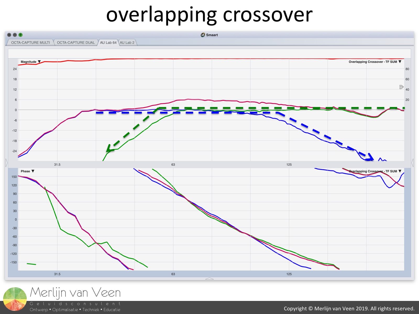 figure 6What we've achieved so far, is known as an overlapping crossover, because both loudspeakers are still running in their full-range "native" mode where high- and low-pass filters haven't been applied yet (figure 6).
Only at unity gain, in the frequency span where both loudspeakers are virtually equally loud because of the overlap, will you observe summation of as much as 6 dB which leaves us with a residual bump, a surplus, that's not part of the sonic signature of either loudspeaker.
This can be easily remedied by applying the same, identical, parametric equalization (PEQ) in both output channels of the loudspeaker management system. Making the subwoofer a true low-frequency extension. The processor's input side, in my opinion, should always be reserved for voicing the system!
When the subwoofers are turned up, this "EQ-patch" is no longer required because the crossover shifts up in frequency and effectively becomes a skewed unity crossover which we'll discuss next.
 figure 7In a unity crossover the overlap has been removed, by applying additional low- and high-pass filters on top of the previous alignment, and -6 dB meets -6 dB at a frequency of our choosing (figure 7).
It's advised to choose a convenient crossover frequency close to the center of the previous overlap (figure 5) where both loudspeakers operate at near-identical levels. In this instance 80 Hz.
Again, there's no reason to measure everything again and I could engage these filters blindly (which I did) provided you:
- Use the same constant-slope typology for both loudspeakers
i.e., Butterworth and Linkwitz-Riley - Use the same even filter orders for both loudspeakers
i.e., 2nd, 4th, 6th, 8th, etc. (certain orders might require polarity reversal) - Use the same corner frequency for both lousdpeakers
Sticking to these pointers will affect the phase response of both loudspeakers equally. Consequentially, what was phase aligned before the introduction of the filters should remain phase aligned after introducing the filters with exception of the occasional polarity reversal depending on the filter order.
I always default to Linkwitz-Riley (also in these video examples) which conveniently introduces 6 dB of attenuation at the corner frequency, in contrast to Butterworth which introduces only 3 dB of attenuation at the corner frequency, leaving you with a 3 dB bump for loudspeakers that where equally loud at the crossover frequency prior to introducing the filters.
That being said, there are superior filters, involving complex slopes, e.g., Elliptic and Chebyshev filters, which are of more interest but also beyond the scope of this article. However, all the steps described in this procedure will make those work for you as well!
In an appropriately phase aligned crossover at unity gain, where -6 dB meets -6 dB at the crossover frequency, the outcome will be 0 dB when both loudspeakers are turned on together. Unlike the overlapping crossover, there's no residual bump or surplus which requires an additional PEQ-patch.
Which order to choose
From what I am able to tell, the majority of the industry appears to have settled for 4th order crossovers (regardless of the typology), with 24 dB per octave slopes, for reasons beyond the scope of this article.
In my book however, this constitutes 4th order acoustical crossovers which is the compound result of electronics in concert with the mechanical-acoustical properties of the loudspeakers themselves.
Therefor, I would never pursuit a 4th order electrical crossover straight out of the gate. When you apply these high- and low-pass filters to the loudspeakers you're trying to shave of one to two-thirds of on octave of bandwidth at most.
However, the loudspeakers themselves come with natural "native" frequency roll-offs which define their operational range. In unity crossovers, you're cutting awfully close to these natural roll-offs and should be mindful of the compound effect of electronics in concert with mechanical-acoustics.
Figure 7 contains red arrows indicating actual 4th order, 24 dB per octave slopes. Notice that the 4th order electrical filters in concert with the natural roll-offs, produce slopes which are too steep in the frequency range of interest, for no good reason! That's why I encourage restraint with electronic filters and recommend to start with lower-order filters first.
Typically, 2nd order, this close to the natural roll-offs, works nicely while avoiding the unnecessary introduction of extra, unjustified, phase shift, inherent to higher-order filters, to a part of the frequency spectrum where most loudspeakers are already sluggish by design!
In medicine, the principal precept is; first do no harm. The same can be said for introducing phase shift. Less is more! Consult this article on group delay to understand why.
Up to twelve
Key is to understand that our high- and low-pass filters haven't affected the corridor's length or extend which still lasts till 250 Hz like before, provided you stick to the pointers mentioned earlier!
The low-pass filter assigned to the subwoofer, reduced its bandwidth which effectively expedites the onset of main loudspeaker isolation. The subwoofer level can now be increased by as much as +45 dB with respect to the main loudspeaker (20 dB more than with the overlapping crossover) before the corridor of 60° comes to an end and isolation becomes mandatory. Eat your heart out!
Presets
What we've basically been doing so far, is creating our own presets while being equidistant, ergo equitemporal, to the flush, coplanar loudspeaker grills. A process which colloquially can be thought of as "pre-alignment". And while doing so, we set the delay finder only once!
However, in today's industry, most of the time, these steps have already been taken by the manufacturer provided you RTFM and use factory-recommended settings. Why wouldn't they? It's the sensible thing to do which keeps the phone from ringing.
If tops and subs are supposed to be flown in a single "banana", e.g., line array (including ground-stacked), I sure hope the system is appropriately phase aligned when the grills are flush, because that's how it has been deployed and the same could be said for pole-mounted loudspeakers living on top of subwoofers.
However, never ever take this for granted and convince yourself first, in person, before proceeding with the absolute part!
In the unlikely case that a manufacturer hasn't made sure that these conditions are met, you have to execute these steps yourself. However, it's set-and-forget. You only have to do it once.
If you make your own presets, you probably want take note of the following properties:
- subwoofer model
- main loudspeaker model
- overlapping or unity crossover (including crossover frequency)
- max LF with respect to the mains (determined by the corridor of 60°)
These properties should be easy to tell from the preset name you come up with.
The absolute part
When main loudspeakers and subwoofers are deployed in actual venues, they don't necessarily end up in the same location or in any other way that ensures that the audience members remain equidistant and therefor equitemporal to their grills. This is when "shit hits the fans" (plural).
Most of the time, we can fix this for one point in space only (it's a geometrical problem) and it's one of few instances (depending on the circumstances) where I'm likely to choose the front-of-house position (FOH) and put all means at the king's disposal (monarchy). Provided, the FOH position is sensibly located, anywhere from fifty to one hundred percent venue-depth.
I do this for the sole purpose of preventing that the FOH-engineer ends up, unforeseen, despite our best efforts, in a null for a particular frequency throughout the crossover region which he or she is likely going to try to fix with EQ. However, a level-band-aid is not gonna remedy a time problem. It will not improve the situation at FOH and make things worse for all other audience members!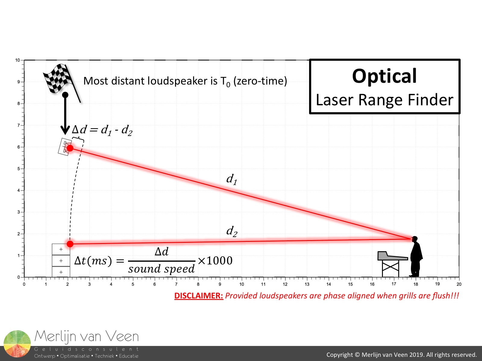 figure 8
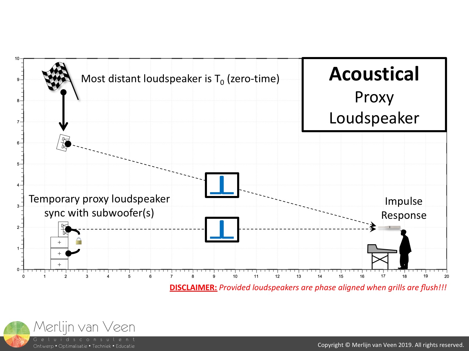 figure 9In the scenario shown in figures 8 and 9, the FOH-engineer is no longer equidistant to the grills, the very condition that needs to be met in order for the presets to work.
The subwoofer grills are physically closer and therefor leading. This can be addressed by giving the subwoofers a "virtual push" by means of delay. The amount of delay can be determined in two ways.
The optical way (figure 8) requires you the measure, preferably using a laser range finder, the difference in trajectories and convert that physical offset into time. The acoustical way (figure 9) makes use of a so-called proxy loudspeaker.
Delay finders struggle with subwoofers because subwoofers reproduce only a fraction of the audible spectrum leaving too little data for the delay finder to lock onto.
Read this article to gain more insight as to why.
The proxy loudspeaker's sole purpose is to add the frequencies which are missing from the subwoofer, allowing the delay finder to detect arrival time again.
For this to work, it's mission critical that you use the same make and loudspeaker model with the same preset as the main loudspeaker!
This loudspeaker will sit flush, on top of the subwoofers, with its grill living in the same plane as those of the subwoofers. The very condition which makes the preset work. There, it will act as "ambassador" for the subwoofers underneath.
Under these circumstances, we can synchronize the delay finder to the main loudspeaker in which case the proxy loudspeaker will be leading because its grill is physically closer. The impulse response will inform you by how much.
Consequentially, if the proxy loudspeaker is leading, then so are the subwoofers living underneath the proxy loudspeaker. To make the main and proxy loudspeakers arrive in time would require us to delay the proxy loudspeaker and inherently the subwoofers which are represented by the proxy loudspeaker.
Either approach for determining the time offset (optical or acoustical) takes little to no time which I hope you're able to appreciate. Whatever time offset is found, is then added to whichever grill is physically closer (in this case the subwoofer) on top of whatever it took to make the preset work in the first place!
Once the proxy loudspeaker has served its purpose, you can strike it, reattach it to the bottom of the array (in case of a line array) or keep it as fill loudspeaker to add fresh and intelligible, mid- and high-frequencies to the subwoofers.
Conclusion
The relative/absolute method's success relies entirely on your time spent in the near field. However, only if you've convinced yourself, in person, that the system is appropriately phase aligned when the grills are flush, will the absolute part work.
In exchange, the absolute part will take very little time on site and comfortably get you in the "ballpark". Afterwards, if you have time and energy left over, you can consider verifying acoustically if the phase aligned crossover has survived.
However, allow me to remind you that the loudspeaker's phase response, within its intended coverage, typically doesn't change over distance, unless you actually did something to the loudspeaker that invokes actual phase shift, i.e., applying filters of some sort which you should be able to rule out!
Room interaction however, will make it appear like the loudspeaker's phase response is changing over distance because the room makes the traces go FUBAR. Don't judge a book by its cover.
However, if you paid your dues in the near field, you should have near-anechoic traces (I think of them as Polaroids) that inform you how the appropriately aligned crossover is supposed to look which you can then use to identify your far field success once the room enters your measurements.
DISCLAIMER: I kindly request you to not reach out to me to inform me that the absolute part doens't work without proving that the relative part was sorted first.